

Custom designed for your application
Positive Drive Chain Edge (PDCE)
Positive Drive Conveyor Belts for Exacting Applications.
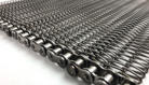
When your application requires positive drive, indexing or synchronization, a chain edge design is the practical choice. Positive drive conveyor belt assemblies employing a chain edge are also widely used due to their uniformity in pitch, high tensile strength with relatively light belt/chain weight, and good durability under severe loads.
Positive Drive Chain Edge (PDCE)
Features
Specifications
Options
Downloads
Features
CUSTOM DESIGNED FOR YOUR APPLICATION
PDCE are truly custom conveyor belts, whereby either standard or special chains are added to a custom designed support system for your product and process. PDCE conveyor belts can be produced using many different materials including various grades of malleable iron, high strength cast alloys, heat treatable malleable iron, stainless and carbon steel.
ASHWORTH BELTING PROFESSIONALS ARE READY TO ASSIST YOU
Many different wire mesh configurations are available, including balance weave, compound balance weave and conventional weave. Plastic modules are also available to serve as the product support surface. However, the appropriate wire mesh or module is both application and belt support member specific. Ashworth belting professionals stand ready to assist you in selecting the proper combination of chain, cross supports and mesh overlay, plus any required guard edge plates, lifts or lane dividers to meet your specific requirements.
For Exacting Applications
- Uniform in pitch
- Straight tracking
- High tensile strength
- Durable under severe loads
- Longer belt life than pin roll drives
Application Options
- Choose from a variety of chain weights and strengths
- Customize with different conveyor meshes or plastic modules
- Available with guard edges, lifts and/or lane dividers
Design Assistance
- Ashworth's Belt Professionals stand ready to assist you in selecting the proper variations and options for your specific application
DIRECTION

STRAIGHT RUN
APPLICATIONS

SMOKER

COOKER

DRYER

FRYER
Does this meet your project needs?
Does this meet your project needs?
Does this meet your project needs?
Let’s get started!
Let’s get started!
Let’s get started!
Specifications
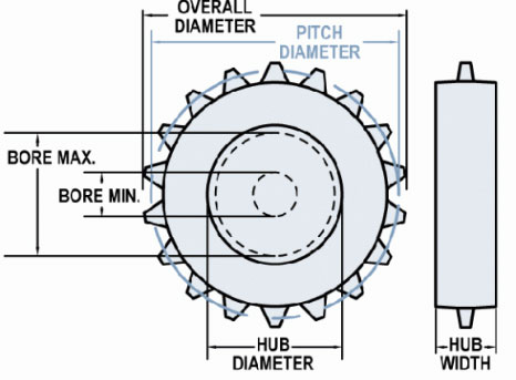
Available Sprocket Options
Sprocket Reference
Select another sprocket size
Select a product
| Nom. Size | Display | Teeth | Pitch Diameter in (mm) | Hub Diameter in (mm) | Bore Min in (mm) | Bore Max in (mm) |
|---|---|---|---|---|---|---|
| 3 | 2052B8 CS | 8 | 3.27 (82.96) | 2.52 (63.91) | 0.62 (15.88) | 1.9 (48.26) |
| 4 | 2052B10 T304 | 10 | 4.05 (102.74) | 3.3 (83.69) | 0 | 2.55 (64.77) |
| 5 | 2052B13 CS | 13 | 5.22 (132.66) | 4.43 (112.65) | 0 | 3.45 (87.63) |
| 10 | 2052B26 CS | 26 | 10.37 (263.4) | 9.62 (244.35) | 0 | 8.13 (206.5) |
Material Reference
- Acetal - polyoxymethylene plastic
- Celcon - acetal copolymer
- CI - cast iron
- Hardened Steel
- Nylon
- T303 - stainless steel
- T316 - stainless steel
- UMHW - polyethylene plastic
| Technical Specifications | |
|---|---|
|
Available Materials (Mesh and Connector Rods) |
Stainless steel, carbon and galvanized steels, high temperature seel alloys |
| Minimum Width* | Defined by customer specfied chain and mesh widths |
| Maximum Mesh Width* | No absolute maximum width; dependent on customer appliation and belt specifications |
| Conveying Surface | Equal to mesh width or inside guard edge dimension if guard edges are used |
| Weight | Dependent on mesh, rod, and chain weights |
| Allowable Tension | Defined by chain strength |
| Available Mesh Types | Balanced weave, compound balanced weave, or conventional weave |
| Turn Capability | Straight run only |
| Maximum Temperature | Dependent on chain type and material |
| Method of Drive | Positive drive via matching chain and sprockets |
Notes
PDCE belt assemblies employing metal roller chains are widely used in conveyor applications because of uniformity of pitch, high tensile strength and relatively light weight. An almost unlimited variety of custom-designed PDCE belts are possible, combining the numerous types of mesh, chain, and cross supports (rods).
Chains
Roller Chains
Ashworth can incorporate almost any precision roller chain; such as RC50, C2060H, or C2082H. Chain types can be either single or double pitch, and double pitch chains can have either a standard or oversized roller.
Engineering Class Bushed Roller Chains are all-steel chains, appropriate for heavy-duty service and for difficult operating conditions. Heavy duty, long pitch oversized roller chains are also commercially available and may be incorporated in PDCE belts.
Drag Chains
Drag chains are defined as any chain that does not have a roller. Pintle chains fall into this class and have great durability and will handle medium loads at low speeds. Fabricated from malleable iron, they will operate satisfactorily at temperatures up to 600°F (316°C). For handling heavy loads, a high strength cast alloy is recommended. For severely corrosive conditions or temperatures in excess of 1050°F( 566°C), several types of cast stainless steel alloys are available.
Detachable link chains are also available in either malleable iron or pressed steel, Positive drive conveyors employing detachable link chains are used in applications with light loads and slow speeds. these chains must be well lubricated and are normally used where nonabrasive operating conditions exist.
Chain manufacturers' catalogs afford complete data, specifications, and types of attachments available for all types of chains that can be incorporated into Ashworth PDCE belts.
Mesh
A PDCE belt's mesh can be of any balanced weave, compound balance weave or conventional weave variety. However, the second count (SC) number is a function of cross support spacing, unless a special spiral* is used or the cross support is attached to the underside of the mesh. (For more infomation see the section on "Mesh Designation for Woven Wire Belts".)
Meshes on PDCE belts can be manufactured in one of three ways:
- Thicker than normal mesh is woven to accommodate the cross supports, which are inserted through the spirals. The spirals are all of uniform size throughout the belt.
- Mesh is of standard thickness but is interspersed iwth special spirals* to accomodate large cross supports or when a very dense mesh is specified.
- Mesh is of standard thickness and is attached to the top of the cross supports (flat bars channels or angles).
* A special spiral is larger than a standard spiral and can be manufactured in various shapes such as oval, diamond, square, etc..
Cross Supports
Rods
Rods are frequently used as cross supports. Their length is generally the same as the overall width of the belt. Rod edges are either welded, washer welded, brazed, washer brazed, or drilled and cottered as specified. winced rods are used to hold the chain sideplates in place when pin-size rods are used with either riveted hollow pins or cottered chains, and are located on every chain pitch. When used as cross supports and engage the chain as pins, the standard size of the rods is a follows:
| ANSI Number | Rod Diameter |
|---|---|
| RC35 and RC41 | 0.135" (3.4 mm) |
| RC40, C2040, & C2042 | 0.152" (3.9 mm) |
| RC50, C2050 & C2052 | 0.196" (5.0 mm) |
| RC60, C2060H & C2062H | 0.230" (5.8 mm) |
| RC80, C2080H & C2082H | 0.307" (7.8 mm) |
Pipe/Rod
Rods can be inserted through any pipe or tubing which is commercially available and the combination is then inserted through the mesh. the pipe/tubing length is typically the same width as the mesh.
Turned-Down Rod
When the rod diameter is oversized for the chain according to the previous chart, the ends of the rods can be turned down to the standard pin diameter to engage the chain.
Channel or Angle
any commercially-made or manufactured channel or angle available may be used as cross supports. These are normally plug-welded or brazed to the underside of mesh. In general, channel or angle cross supports are bolted to a chin attachment, but in some cases are welded to the chain sideplate.
Flat Bar
Any commercially made or manufactured flat bar available may be used as cross supports. The flat bar's length is determined by type of chain used and its attachment. the flat bar may be inserted through the mesh or attached to the underside of mesh as specified. When attached to the underside, the flat bar is plug-welded or brazed to the mesh through slots or holes in the flat bar. In general, the flat bar is bolted to the chain, but in some cases it is welded to the chain sideplate.
Available Options
Guard Edges
Guard edges are located on the inside of the chain. Height above the belt surface and material is customer specified. Guard edges are usually used with round cross supports (rods, turned down rods, or pipe/ rod) which are inserted through holes in the guard edge.
Guard edges are generally plates that may be offset, of interlocking design, or flat plates that are assembled in either a shingled or staggered arrangement. Plates can be square or rectangular and either flared or notched as required (Figure 18). Plates with double tabs may be used. The bottom tabs may be inserted through the mesh or the tabs may straddle the mesh and are welded or brazed to it. Whenever guard edges are specified, the inside guard edge (IGE) dimension should be specified by the customer.
Flights (Lifts or Cleats)
Generally, flights are attached to the belt by welding or brazing them to the mesh and/or the guard edges (if applicable). The style, material, height, and spacing above the belt surface is customer specified. The length of the flight is usually the same as the mesh width but can be narrower if specified.
Usually, flights are produced from formed angle stock, although commercially available flat bar, keystock, cut sheet metal, or other customer specified shapes may be used. Angle types usually have slots or holes punched in the bottom to facilitate plug-welding to the mesh. It should be noted that flights are not meant to carry product up inclines but are just to prevent product slippage.
Wipers
Wiper attachments, typically fabricated from wire mesh, hang from the bottom surface of the belt to wipe debris from drip pans, trays, bins, etc. These attachments are typically attached to belt mesh with a straight or crimped connector rod. Mesh designation (if applicable), material, length below belt surface, width of wiper, and spacing are customer specified.

Need more detailed information?
Need more detailed information?
Need more detailed information?
Options
Product Options
Guard Edges
Guard edges are located on the inside of the chain. Height above the belt surface and material is customer specified. Guard edges are usually used with round cross supports (rods, turned down rods, or pipe/ rod) which are inserted through holes in the guard edge.
Guard edges are generally plates that may be offset, of interlocking design, or flat plates that are assembled in either a shingled or staggered arrangement. Plates can be square or rectangular and either flared or notched as required (Figure 18). Plates with double tabs may be used. The bottom tabs may be inserted through the mesh or the tabs may straddle the mesh and are welded or brazed to it. Whenever guard edges are specified, the inside guard edge (IGE) dimension should be specified by the customer.
Flights (Lifts or Cleats)
Generally, flights are attached to the belt by welding or brazing them to the mesh and/or the guard edges (if applicable). The style, material, height, and spacing above the belt surface is customer specified. The length of the flight is usually the same as the mesh width but can be narrower if specified.
Usually, flights are produced from formed angle stock, although commercially available flat bar, keystock, cut sheet metal, or other customer specified shapes may be used. Angle types usually have slots or holes punched in the bottom to facilitate plug-welding to the mesh. It should be noted that flights are not meant to carry product up inclines but are just to prevent product slippage.
Wipers
Wiper attachments, typically fabricated from wire mesh, hang from the bottom surface of the belt to wipe debris from drip pans, trays, bins, etc. These attachments are typically attached to belt mesh with a straight or crimped connector rod. Mesh designation (if applicable), material, length below belt surface, width of wiper, and spacing are customer specified.
Downloads
Downloads
Technical Bulletins
Installation, Assembly & Maintenance Instructions
Conveyor System Review Form
Illustrations
-
 PDCE RS60 .375ROD1.5CC B36 16 16
-
PDCE 60HP .23ROD CENTER CHAIN 53.66BW
-
PDCE C2040 B60 24 1416 .25RODS 37.19BW
-
PDCE C2042 B144 24 20 .307R 36BW
-
PDCE C2062H B30 16 16 .23ROD
-
PDCE C2080H B60 24 16 .307ROD
-
PDCE C2080H B72 24 16C ROD 74.94BW
-
PDCE C2080H B72 24 16C ROD 98.9Bwpdf
-
PDCE C2082H B60 15 16 .5RODS
-
PDCE C2082HP B60 18 18 16 BAFFLE SKID LINK
-
PDCE C2100H B72 19.2 16
-
PDCE R40 B36 36 16 .152ROD.Dwg
-
PDCE RS40 B72 24 1618 .152R GEN
-
PDCE RS40 B72 36 1618 .152R GEN
-
PDCE RS80HP .307ROD1CC 48BW


