


Hygienic and sanitary conveyor belting
Flat Wire Conveyor Belts
Ashworth began manufacturing flat wire conveyor belts in 1951, and they are still among the most versatile and most economical straight-running belts available.
Features
Specifications
Options
Downloads
Features
These belts are engineered and manufactured to strict tolerances resulting in a longer belt life.
Features and Benefits
Efficient Performance
- Maximum open area minimizes spray deflection
- Versatile to suit most applications: standard weight and heavy duty variants are available
Proven Reliability
- Precision manufactured using the industry's tightest tolerances for increased belt life and smooth operation
- Over 75 years of customer satisfaction
DIRECTION

STRAIGHT RUN
APPLICATIONS

FREEZER

SMOKER

COOLER

COOKER

DRYER

FRYER

PROOFER

BLANCHER

PASTEURIZING

GRADING

TRANSFER

PACKAGING
Does this meet your project needs?
Does this meet your project needs?
Does this meet your project needs?
Let’s get started!
Let’s get started!
Let’s get started!
Specifications
Technical Specifications
Select another product option
| Technical Specifications | Units | FWA1 |
|---|---|---|
| Rod Diameter | in. [mm] | 0.106 [2.69] |
| Picket Dimension | 0.375 x 0.046 [9.5 x 1.2] | |
| Nominal Mesh Opening | in. | 1 By 1 |
| Edge Treatment | Clinched | |
| Available Widths | in. [mm] | 4.5-208 [114-5283.20] |
| Conveying Surface | Belt width -0 | |
| Longitudinal Pitch | in. [mm] | 1.07 [27.23] |
| Open Area | 68% | |
| Maximum Allowable Tension | 350 [522] | |
| Method of Drive | Positively driven with matching sprockets or friction driven with a flat faced drum |
Available Sprocket Options
Sprocket Reference
Select another sprocket size
Select a product
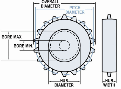
| Nom. Size | Display | Teeth | Pitch Diameter in (mm) | Hub Diameter in (mm) | Bore Min in (mm) | Bore Max in (mm) |
|---|---|---|---|---|---|---|
| 3 | #3-8 T303 | 8 | 2.81 (71.35) | 2.2 (55.88) | 0 | 1.64 (41.66) |
| 4 | #4-13 Celcon | 13 | 4.48 (113.77) | 3.9 (99.06) | 1 (25.4) | 3.04 (77.22) |
| 4 | #4-13 CI | 13 | 4.47 (113.51) | 3.97 (100.81) | 0 | 3.1 (78.74) |
| 4 | #4-13 T303 | 13 | 4.48 (113.77) | 3.97 (100.84) | 0 | 3.11 (78.99) |
| 4 | #4-13 T316 | 13 | 4.48 (113.77) | 3.97 (100.84) | 0 | 3.11 (78.99) |
| 4 | #4-13 UHMW | 13 | 4.48 (113.77) | 3.9 (99.06) | 1 (25.4) | 2.91 (73.91) |
| 6 | #6-18 CI | 18 | 6.19 (157.16) | 5.69 (144.46) | 0 | 3.75 (95.25) |
| 6 | #6-18 T316 | 18 | 6.19 (157.16) | 5.69 (144.46) | 0 | 3.75 (95.25) |
| 6 | #6-18 UHMW | 18 | 6.19 (157.16) | 5.65 (143.46) | 1 (25.4) | 4.29 (108.97) |
| 8 | #8-23 CI | 23 | 7.88 (200.02) | 7.44 (188.93) | 0 | 5.96 (151.38) |
| 8 | #8-23 CI | 23 | 7.88 (200.02) | 7.44 (188.91) | 0 | 4.75 (120.65) |
| 8 | #8-23 CI | 23 | 7.88 (200.02) | 7.44 (188.93) | 0 | 5.96 (151.38) |
| 8 | #8-23 T316 | 23 | 7.88 (200.02) | 7.44 (188.91) | 0 | 4.75 (120.65) |
| 8 | #8-23 UHMW | 23 | 7.88 (200.02) | 7.39 (187.63) | 1 (25.4) | 5.9 (149.86) |
| 10 | #10-28 UHMW | 28 | 9.6 (243.87) | 9.16 (232.77) | 0 | 7.43 (188.72) |
| 10 | #10-31 CI | 31 | 10.6 (269.14) | 10.16 (257.96) | 0 | 8.67 (220.22) |
| 10 | #10-31 T303 | 31 | 10.6 (269.14) | 10.16 (257.96) | 0 | 8.67 (220.22) |
| 10 | #10-31 T303 | 31 | 10.59 (269.08) | 10.16 (257.97) | 0 | 8.67 (220.22) |
| 10 | #10-31 T316 | 31 | 10.59 (269.08) | 10.16 (257.97) | 0 | 8.67 (220.22) |
| 10 | #10-31 UHMW | 31 | 10.53 (267.59) | 10.16 (258.06) | 1 (25.4) | 8.42 (213.87) |
| 12 | #12-37 CI | 37 | 12.64 (321.06) | 12.21 (310.13) | 0 | 10.72 (272.29) |
| 12 | #12-37 T316 | 37 | 12.64 (321.06) | 12.21 (310.13) | 0 | 10.72 (272.29) |
| 12 | #12-37 T316 A HUB | 37 | 12.64 (321.08) | 12.21 (310.13) | 0 | 4.39 (111.51) |
| 12 | #12-37 UHMW | 37 | 12.6 (319.91) | 12.22 (310.39) | 0.99 (25.02) | 10.48 (266.19) |
UHMWPE material type components have a 150° F (66°C) maximum operation temperature.
13 through 31 tooth sprockets must have tooth height reduced to 3/8" (9.5 mm) for use with standard weight belts.
Maximum bore sized listed for UHMWPE material is based on 1/2 inch (12.7 mm) of material above keyway.
Material Reference
- Acetal - polyoxymethylene plastic
- Celcon - acetal copolymer
- CI - cast iron
- Hardened Steel
- Nylon
- T303 - stainless steel
- T316 - stainless steel
- UMHW - polyethylene plastic
Need more detailed information?
Need more detailed information?
Need more detailed information?
Belt Calculator
No Results
Base Belt Weight
Loop Count
Outer Loop Count
Inner Loop Count
Openings
Inner Openings
Outer Openings
Opening Size
Open Area
Belt Pitch
Turn Ratio
Strength Straight
Strength Turn
Rod Size
Edge Finish
Need more detailed information?
Need more detailed information?
Need more detailed information?
Options
Product Options

Pin-up Attachments
Pin-up attachments are flat wire strips that lift the product from the belt surface to prevent undesirable marking. They can also be used to keep the product from sliding on inclines or declines.
Limits for Use:
- Maximum height above belt surface is 0.38" (9.5 mm)
- Belt must be supported so that the pinup can pass through the return path

Lifts
Lift attachments keep the product from sliding on inclines or declines. The formed angle lift uses a flight clip to fasten it to the belt. The flat bar lift is welded to the belt.
Limits for Use:
-
Maximum Lift Width: Belt Width: - 0.5" (12.7 mm)
-
Lift Thickness: Normal limits are no greater than 0.18" (4.8 mm) or smaller than 0.06" (1.52 mm)
-
Lift Height: Check with Engineering if greater than 6" (152 mm)
-
Minimum Lift Spacing: 2" (50.8 mm)
-
Belt must be supported so that the lift can pass through the return path

Beveled Edges
Beveling the edge of the flat wire pickets facilitates product transfer by eliminating or reducing tippage of sharp edge cans or bottles. This option offers advantages on all transfer operations where the terminal roll or sprocket diameter is smaller than 10" (254 mm).
Does this meet your project needs?
Does this meet your project needs?
Does this meet your project needs?
Let’s get started!
Let’s get started!
Let’s get started!
Downloads
Downloads
Installation, Assembly & Maintenance Instructions
Conveyor System Review Form
Illustrations
-
 Flat Wire A1 1 x 1 - Standard Weight
-
Flat Wire A3 1/2 x 1 - Standard Weight
-
Flat Wire B3 1/2 x 1 - Standard Weight
-
Flat Wire A4 1/2 x 1 - Standard Weight
-
Flat Wire A5 1/2 x 1/2 - Standard Weight
-
Flat Wire B1 1 x 1 - Standard Weight
-
Flat Wire B2 1 x 1 - Standard Weight
-
Flat Wire B4 1/2 x 1 - Standard Weight
-
Flat Wire C1 1 x 1 - Heavy Duty
-
Flat Wire C2 1/2 x 1 - Heavy Duty 2
-
Flat Wire C6 Mod 1/2 x 1/2 - Heavy Duty
-
Flat Wire H3 1/2 x 1 - EZ Transfer
-
FWA1
-
FWA2
-
FWA3
-
FWA4
-
FWA5
-
FWA5SC
-
FWA6
-
FWB1
-
FWB3
-
FWB4
-
FWB5
-
FWB5S
-
FWB6
-
FWC1
-
FWC1C
-
FWC2
-
FWC2C
-
FWC6
-
FWC6SB
-
FWH3
Features
These belts are engineered and manufactured to strict tolerances resulting in a longer belt life.
Features and Benefits
Efficient Performance
- Maximum open area minimizes spray deflection
- Versatile to suit most applications: standard weight and heavy duty variants are available
Proven Reliability
- Precision manufactured using the industry's tightest tolerances for increased belt life and smooth operation
- Over 75 years of customer satisfaction
DIRECTION
STRAIGHT RUN
APPLICATIONS
FREEZER
SMOKER
COOLER
COOKER
DRYER
FRYER
PROOFER
BLANCHER
PASTEURIZING
GRADING
TRANSFER
PACKAGING
Does this meet your project needs?
Does this meet your project needs?
Does this meet your project needs?
Let’s get started!
Let’s get started!
Let’s get started!
Specifications
Technical Specifications
Select another product option
| Technical Specifications | Units | FWA2 |
|---|---|---|
| Rod Diameter | in. [mm] | 0.106 [2.69] |
| Picket Dimension | 0.375 x 0.046 [9.5 x 1.2] | |
| Nominal Mesh Opening | in. | 1 By 1 |
| Edge Treatment | Welded | |
| Available Widths | in. [mm] | 4.5-208 [114-5283.20] |
| Conveying Surface | Belt width -0 | |
| Longitudinal Pitch | in. [mm] | 1.07 [27.23] |
| Open Area | 68% | |
| Maximum Allowable Tension | 350 [522] | |
| Method of Drive | Positively driven with matching sprockets or friction driven with a flat faced drum |
Available Sprocket Options
Sprocket Reference
Select another sprocket size
Select a product
| Nom. Size | Display | Teeth | Pitch Diameter in (mm) | Hub Diameter in (mm) | Bore Min in (mm) | Bore Max in (mm) |
|---|---|---|---|---|---|---|
| 3 | #3-8 T303 | 8 | 2.81 (71.35) | 2.2 (55.88) | 0 | 1.64 (41.66) |
| 4 | #4-13 Celcon | 13 | 4.48 (113.77) | 3.9 (99.06) | 1 (25.4) | 3.04 (77.22) |
| 4 | #4-13 CI | 13 | 4.47 (113.51) | 3.97 (100.81) | 0 | 3.1 (78.74) |
| 4 | #4-13 T303 | 13 | 4.48 (113.77) | 3.97 (100.84) | 0 | 3.11 (78.99) |
| 4 | #4-13 T316 | 13 | 4.48 (113.77) | 3.97 (100.84) | 0 | 3.11 (78.99) |
| 4 | #4-13 UHMW | 13 | 4.48 (113.77) | 3.9 (99.06) | 1 (25.4) | 2.91 (73.91) |
| 6 | #6-18 CI | 18 | 6.19 (157.16) | 5.69 (144.46) | 0 | 3.75 (95.25) |
| 6 | #6-18 T316 | 18 | 6.19 (157.16) | 5.69 (144.46) | 0 | 3.75 (95.25) |
| 6 | #6-18 UHMW | 18 | 6.19 (157.16) | 5.65 (143.46) | 1 (25.4) | 4.29 (108.97) |
| 8 | #8-23 CI | 23 | 7.88 (200.02) | 7.44 (188.93) | 0 | 5.96 (151.38) |
| 8 | #8-23 CI | 23 | 7.88 (200.02) | 7.44 (188.91) | 0 | 4.75 (120.65) |
| 8 | #8-23 CI | 23 | 7.88 (200.02) | 7.44 (188.93) | 0 | 5.96 (151.38) |
| 8 | #8-23 T316 | 23 | 7.88 (200.02) | 7.44 (188.91) | 0 | 4.75 (120.65) |
| 8 | #8-23 UHMW | 23 | 7.88 (200.02) | 7.39 (187.63) | 1 (25.4) | 5.9 (149.86) |
| 10 | #10-28 UHMW | 28 | 9.6 (243.87) | 9.16 (232.77) | 0 | 7.43 (188.72) |
| 10 | #10-31 CI | 31 | 10.6 (269.14) | 10.16 (257.96) | 0 | 8.67 (220.22) |
| 10 | #10-31 T303 | 31 | 10.6 (269.14) | 10.16 (257.96) | 0 | 8.67 (220.22) |
| 10 | #10-31 T303 | 31 | 10.59 (269.08) | 10.16 (257.97) | 0 | 8.67 (220.22) |
| 10 | #10-31 T316 | 31 | 10.59 (269.08) | 10.16 (257.97) | 0 | 8.67 (220.22) |
| 10 | #10-31 UHMW | 31 | 10.53 (267.59) | 10.16 (258.06) | 1 (25.4) | 8.42 (213.87) |
| 12 | #12-37 CI | 37 | 12.64 (321.06) | 12.21 (310.13) | 0 | 10.72 (272.29) |
| 12 | #12-37 T316 | 37 | 12.64 (321.06) | 12.21 (310.13) | 0 | 10.72 (272.29) |
| 12 | #12-37 T316 A HUB | 37 | 12.64 (321.08) | 12.21 (310.13) | 0 | 4.39 (111.51) |
| 12 | #12-37 UHMW | 37 | 12.6 (319.91) | 12.22 (310.39) | 0.99 (25.02) | 10.48 (266.19) |
UHMWPE material type components have a 150° F (66°C) maximum operation temperature.
13 through 31 tooth sprockets must have tooth height reduced to 3/8" (9.5 mm) for use with standard weight belts.
Maximum bore sized listed for UHMWPE material is based on 1/2 inch (12.7 mm) of material above keyway.
Material Reference
- Acetal - polyoxymethylene plastic
- Celcon - acetal copolymer
- CI - cast iron
- Hardened Steel
- Nylon
- T303 - stainless steel
- T316 - stainless steel
- UMHW - polyethylene plastic
Need more detailed information?
Need more detailed information?
Need more detailed information?
Belt Calculator
No Results
Base Belt Weight
Loop Count
Outer Loop Count
Inner Loop Count
Openings
Inner Openings
Outer Openings
Opening Size
Open Area
Belt Pitch
Turn Ratio
Strength Straight
Strength Turn
Rod Size
Edge Finish
Need more detailed information?
Need more detailed information?
Need more detailed information?
Options
Product Options
Pin-up Attachments
Pin-up attachments are flat wire strips that lift the product from the belt surface to prevent undesirable marking. They can also be used to keep the product from sliding on inclines or declines.
Limits for Use:
- Maximum height above belt surface is 0.38" (9.5 mm)
- Belt must be supported so that the pinup can pass through the return path
Lifts
Lift attachments keep the product from sliding on inclines or declines. The formed angle lift uses a flight clip to fasten it to the belt. The flat bar lift is welded to the belt.
Limits for Use:
-
Maximum Lift Width: Belt Width: - 0.5" (12.7 mm)
-
Lift Thickness: Normal limits are no greater than 0.18" (4.8 mm) or smaller than 0.06" (1.52 mm)
-
Lift Height: Check with Engineering if greater than 6" (152 mm)
-
Minimum Lift Spacing: 2" (50.8 mm)
-
Belt must be supported so that the lift can pass through the return path
Beveled Edges
Beveling the edge of the flat wire pickets facilitates product transfer by eliminating or reducing tippage of sharp edge cans or bottles. This option offers advantages on all transfer operations where the terminal roll or sprocket diameter is smaller than 10" (254 mm).
Does this meet your project needs?
Does this meet your project needs?
Does this meet your project needs?
Let’s get started!
Let’s get started!
Let’s get started!
Downloads
Downloads
Installation, Assembly & Maintenance Instructions
Conveyor System Review Form
Illustrations
-
Flat Wire A1 1 x 1 - Standard Weight
-
Flat Wire A3 1/2 x 1 - Standard Weight
-
Flat Wire B3 1/2 x 1 - Standard Weight
-
Flat Wire A4 1/2 x 1 - Standard Weight
-
Flat Wire A5 1/2 x 1/2 - Standard Weight
-
Flat Wire B1 1 x 1 - Standard Weight
-
Flat Wire B2 1 x 1 - Standard Weight
-
Flat Wire B4 1/2 x 1 - Standard Weight
-
Flat Wire C1 1 x 1 - Heavy Duty
-
Flat Wire C2 1/2 x 1 - Heavy Duty 2
-
Flat Wire C6 Mod 1/2 x 1/2 - Heavy Duty
-
Flat Wire H3 1/2 x 1 - EZ Transfer
-
FWA1
-
FWA2
-
FWA3
-
FWA4
-
FWA5
-
FWA5SC
-
FWA6
-
FWB1
-
FWB3
-
FWB4
-
FWB5
-
FWB5S
-
FWB6
-
FWC1
-
FWC1C
-
FWC2
-
FWC2C
-
FWC6
-
FWC6SB
-
FWH3
Features
These belts are engineered and manufactured to strict tolerances resulting in a longer belt life.
Features and Benefits
Efficient Performance
- Maximum open area minimizes spray deflection
- Versatile to suit most applications: standard weight and heavy duty variants are available
Proven Reliability
- Precision manufactured using the industry's tightest tolerances for increased belt life and smooth operation
- Over 75 years of customer satisfaction
DIRECTION
STRAIGHT RUN
APPLICATIONS
FREEZER
SMOKER
COOLER
COOKER
DRYER
FRYER
PROOFER
BLANCHER
PASTEURIZING
GRADING
TRANSFER
PACKAGING
Does this meet your project needs?
Does this meet your project needs?
Does this meet your project needs?
Let’s get started!
Let’s get started!
Let’s get started!
Specifications
Technical Specifications
Select another product option
| Technical Specifications | Units | FWA3 |
|---|---|---|
| Rod Diameter | in. [mm] | 0.106 [2.69] |
| Picket Dimension | 0.375 x 0.046 [9.5 x 1.2] | |
| Nominal Mesh Opening | in. | 1/2 By 1 |
| Edge Treatment | Clinched | |
| Available Widths | in. [mm] | 4.5-208 [114-5283.20] |
| Conveying Surface | Belt width -0 | |
| Longitudinal Pitch | in. [mm] | 1.07 [27.23] |
| Open Area | 66% | |
| Maximum Allowable Tension | 500 [745] | |
| Method of Drive | Positively driven with matching sprockets or friction driven with a flat faced drum |
Available Sprocket Options
Sprocket Reference
Select another sprocket size
Select a product
| Nom. Size | Display | Teeth | Pitch Diameter in (mm) | Hub Diameter in (mm) | Bore Min in (mm) | Bore Max in (mm) |
|---|---|---|---|---|---|---|
| 3 | #3-8 T303 | 8 | 2.81 (71.35) | 2.2 (55.88) | 0 | 1.64 (41.66) |
| 4 | #4-13 Celcon | 13 | 4.48 (113.77) | 3.9 (99.06) | 1 (25.4) | 3.04 (77.22) |
| 4 | #4-13 CI | 13 | 4.47 (113.51) | 3.97 (100.81) | 0 | 3.1 (78.74) |
| 4 | #4-13 T303 | 13 | 4.48 (113.77) | 3.97 (100.84) | 0 | 3.11 (78.99) |
| 4 | #4-13 T316 | 13 | 4.48 (113.77) | 3.97 (100.84) | 0 | 3.11 (78.99) |
| 4 | #4-13 UHMW | 13 | 4.48 (113.77) | 3.9 (99.06) | 1 (25.4) | 2.91 (73.91) |
| 6 | #6-18 CI | 18 | 6.19 (157.16) | 5.69 (144.46) | 0 | 3.75 (95.25) |
| 6 | #6-18 T316 | 18 | 6.19 (157.16) | 5.69 (144.46) | 0 | 3.75 (95.25) |
| 6 | #6-18 UHMW | 18 | 6.19 (157.16) | 5.65 (143.46) | 1 (25.4) | 4.29 (108.97) |
| 8 | #8-23 CI | 23 | 7.88 (200.02) | 7.44 (188.93) | 0 | 5.96 (151.38) |
| 8 | #8-23 CI | 23 | 7.88 (200.02) | 7.44 (188.91) | 0 | 4.75 (120.65) |
| 8 | #8-23 CI | 23 | 7.88 (200.02) | 7.44 (188.93) | 0 | 5.96 (151.38) |
| 8 | #8-23 T316 | 23 | 7.88 (200.02) | 7.44 (188.91) | 0 | 4.75 (120.65) |
| 8 | #8-23 UHMW | 23 | 7.88 (200.02) | 7.39 (187.63) | 1 (25.4) | 5.9 (149.86) |
| 10 | #10-28 UHMW | 28 | 9.6 (243.87) | 9.16 (232.77) | 0 | 7.43 (188.72) |
| 10 | #10-31 CI | 31 | 10.6 (269.14) | 10.16 (257.96) | 0 | 8.67 (220.22) |
| 10 | #10-31 T303 | 31 | 10.6 (269.14) | 10.16 (257.96) | 0 | 8.67 (220.22) |
| 10 | #10-31 T303 | 31 | 10.59 (269.08) | 10.16 (257.97) | 0 | 8.67 (220.22) |
| 10 | #10-31 T316 | 31 | 10.59 (269.08) | 10.16 (257.97) | 0 | 8.67 (220.22) |
| 10 | #10-31 UHMW | 31 | 10.53 (267.59) | 10.16 (258.06) | 1 (25.4) | 8.42 (213.87) |
| 12 | #12-37 CI | 37 | 12.64 (321.06) | 12.21 (310.13) | 0 | 10.72 (272.29) |
| 12 | #12-37 T316 | 37 | 12.64 (321.06) | 12.21 (310.13) | 0 | 10.72 (272.29) |
| 12 | #12-37 T316 A HUB | 37 | 12.64 (321.08) | 12.21 (310.13) | 0 | 4.39 (111.51) |
| 12 | #12-37 UHMW | 37 | 12.6 (319.91) | 12.22 (310.39) | 0.99 (25.02) | 10.48 (266.19) |
UHMWPE material type components have a 150° F (66°C) maximum operation temperature.
13 through 31 tooth sprockets must have tooth height reduced to 3/8" (9.5 mm) for use with standard weight belts.
Maximum bore sized listed for UHMWPE material is based on 1/2 inch (12.7 mm) of material above keyway.
Material Reference
- Acetal - polyoxymethylene plastic
- Celcon - acetal copolymer
- CI - cast iron
- Hardened Steel
- Nylon
- T303 - stainless steel
- T316 - stainless steel
- UMHW - polyethylene plastic
Need more detailed information?
Need more detailed information?
Need more detailed information?
Belt Calculator
No Results
Base Belt Weight
Loop Count
Outer Loop Count
Inner Loop Count
Openings
Inner Openings
Outer Openings
Opening Size
Open Area
Belt Pitch
Turn Ratio
Strength Straight
Strength Turn
Rod Size
Edge Finish
Need more detailed information?
Need more detailed information?
Need more detailed information?
Options
Product Options
Pin-up Attachments
Pin-up attachments are flat wire strips that lift the product from the belt surface to prevent undesirable marking. They can also be used to keep the product from sliding on inclines or declines.
Limits for Use:
- Maximum height above belt surface is 0.38" (9.5 mm)
- Belt must be supported so that the pinup can pass through the return path
Lifts
Lift attachments keep the product from sliding on inclines or declines. The formed angle lift uses a flight clip to fasten it to the belt. The flat bar lift is welded to the belt.
Limits for Use:
-
Maximum Lift Width: Belt Width: - 0.5" (12.7 mm)
-
Lift Thickness: Normal limits are no greater than 0.18" (4.8 mm) or smaller than 0.06" (1.52 mm)
-
Lift Height: Check with Engineering if greater than 6" (152 mm)
-
Minimum Lift Spacing: 2" (50.8 mm)
-
Belt must be supported so that the lift can pass through the return path
Beveled Edges
Beveling the edge of the flat wire pickets facilitates product transfer by eliminating or reducing tippage of sharp edge cans or bottles. This option offers advantages on all transfer operations where the terminal roll or sprocket diameter is smaller than 10" (254 mm).
Does this meet your project needs?
Does this meet your project needs?
Does this meet your project needs?
Let’s get started!
Let’s get started!
Let’s get started!
Downloads
Downloads
Installation, Assembly & Maintenance Instructions
Conveyor System Review Form
Illustrations
-
Flat Wire A1 1 x 1 - Standard Weight
-
Flat Wire A3 1/2 x 1 - Standard Weight
-
Flat Wire B3 1/2 x 1 - Standard Weight
-
Flat Wire A4 1/2 x 1 - Standard Weight
-
Flat Wire A5 1/2 x 1/2 - Standard Weight
-
Flat Wire B1 1 x 1 - Standard Weight
-
Flat Wire B2 1 x 1 - Standard Weight
-
Flat Wire B4 1/2 x 1 - Standard Weight
-
Flat Wire C1 1 x 1 - Heavy Duty
-
Flat Wire C2 1/2 x 1 - Heavy Duty 2
-
Flat Wire C6 Mod 1/2 x 1/2 - Heavy Duty
-
Flat Wire H3 1/2 x 1 - EZ Transfer
-
FWA1
-
FWA2
-
FWA3
-
FWA4
-
FWA5
-
FWA5SC
-
FWA6
-
FWB1
-
FWB3
-
FWB4
-
FWB5
-
FWB5S
-
FWB6
-
FWC1
-
FWC1C
-
FWC2
-
FWC2C
-
FWC6
-
FWC6SB
-
FWH3
Features
These belts are engineered and manufactured to strict tolerances resulting in a longer belt life.
Features and Benefits
Efficient Performance
- Maximum open area minimizes spray deflection
- Versatile to suit most applications: standard weight and heavy duty variants are available
Proven Reliability
- Precision manufactured using the industry's tightest tolerances for increased belt life and smooth operation
- Over 75 years of customer satisfaction
DIRECTION
STRAIGHT RUN
APPLICATIONS
FREEZER
SMOKER
COOLER
COOKER
DRYER
FRYER
PROOFER
BLANCHER
PASTEURIZING
GRADING
TRANSFER
PACKAGING
Does this meet your project needs?
Does this meet your project needs?
Does this meet your project needs?
Let’s get started!
Let’s get started!
Let’s get started!
Specifications
Technical Specifications
Select another product option
| Technical Specifications | Units | FWA4 |
|---|---|---|
| Rod Diameter | in. [mm] | 0.106 [2.69] |
| Picket Dimension | 0.375 x 0.046 [9.5 x 1.2] | |
| Nominal Mesh Opening | in. | 1/2 By 1 |
| Edge Treatment | Welded | |
| Available Widths | in. [mm] | 4.5-208 [114-5283.20] |
| Conveying Surface | Belt width -0 | |
| Longitudinal Pitch | in. [mm] | 1.07 [27.23] |
| Open Area | 66% | |
| Maximum Allowable Tension | 500 [745] | |
| Method of Drive | Positively driven with matching sprockets or friction driven with a flat faced drum |
Available Sprocket Options
Sprocket Reference
Select another sprocket size
Select a product
| Nom. Size | Display | Teeth | Pitch Diameter in (mm) | Hub Diameter in (mm) | Bore Min in (mm) | Bore Max in (mm) |
|---|---|---|---|---|---|---|
| 3 | #3-8 T303 | 8 | 2.81 (71.35) | 2.2 (55.88) | 0 | 1.64 (41.66) |
| 4 | #4-13 Celcon | 13 | 4.48 (113.77) | 3.9 (99.06) | 1 (25.4) | 3.04 (77.22) |
| 4 | #4-13 CI | 13 | 4.47 (113.51) | 3.97 (100.81) | 0 | 3.1 (78.74) |
| 4 | #4-13 T303 | 13 | 4.48 (113.77) | 3.97 (100.84) | 0 | 3.11 (78.99) |
| 4 | #4-13 T316 | 13 | 4.48 (113.77) | 3.97 (100.84) | 0 | 3.11 (78.99) |
| 4 | #4-13 UHMW | 13 | 4.48 (113.77) | 3.9 (99.06) | 1 (25.4) | 2.91 (73.91) |
| 6 | #6-18 CI | 18 | 6.19 (157.16) | 5.69 (144.46) | 0 | 3.75 (95.25) |
| 6 | #6-18 T316 | 18 | 6.19 (157.16) | 5.69 (144.46) | 0 | 3.75 (95.25) |
| 6 | #6-18 UHMW | 18 | 6.19 (157.16) | 5.65 (143.46) | 1 (25.4) | 4.29 (108.97) |
| 8 | #8-23 CI | 23 | 7.88 (200.02) | 7.44 (188.93) | 0 | 5.96 (151.38) |
| 8 | #8-23 CI | 23 | 7.88 (200.02) | 7.44 (188.91) | 0 | 4.75 (120.65) |
| 8 | #8-23 CI | 23 | 7.88 (200.02) | 7.44 (188.93) | 0 | 5.96 (151.38) |
| 8 | #8-23 T316 | 23 | 7.88 (200.02) | 7.44 (188.91) | 0 | 4.75 (120.65) |
| 8 | #8-23 UHMW | 23 | 7.88 (200.02) | 7.39 (187.63) | 1 (25.4) | 5.9 (149.86) |
| 10 | #10-28 UHMW | 28 | 9.6 (243.87) | 9.16 (232.77) | 0 | 7.43 (188.72) |
| 10 | #10-31 CI | 31 | 10.6 (269.14) | 10.16 (257.96) | 0 | 8.67 (220.22) |
| 10 | #10-31 T303 | 31 | 10.6 (269.14) | 10.16 (257.96) | 0 | 8.67 (220.22) |
| 10 | #10-31 T303 | 31 | 10.59 (269.08) | 10.16 (257.97) | 0 | 8.67 (220.22) |
| 10 | #10-31 T316 | 31 | 10.59 (269.08) | 10.16 (257.97) | 0 | 8.67 (220.22) |
| 10 | #10-31 UHMW | 31 | 10.53 (267.59) | 10.16 (258.06) | 1 (25.4) | 8.42 (213.87) |
| 12 | #12-37 CI | 37 | 12.64 (321.06) | 12.21 (310.13) | 0 | 10.72 (272.29) |
| 12 | #12-37 T316 | 37 | 12.64 (321.06) | 12.21 (310.13) | 0 | 10.72 (272.29) |
| 12 | #12-37 T316 A HUB | 37 | 12.64 (321.08) | 12.21 (310.13) | 0 | 4.39 (111.51) |
| 12 | #12-37 UHMW | 37 | 12.6 (319.91) | 12.22 (310.39) | 0.99 (25.02) | 10.48 (266.19) |
UHMWPE material type components have a 150° F (66°C) maximum operation temperature.
13 through 31 tooth sprockets must have tooth height reduced to 3/8" (9.5 mm) for use with standard weight belts.
Maximum bore sized listed for UHMWPE material is based on 1/2 inch (12.7 mm) of material above keyway.
Material Reference
- Acetal - polyoxymethylene plastic
- Celcon - acetal copolymer
- CI - cast iron
- Hardened Steel
- Nylon
- T303 - stainless steel
- T316 - stainless steel
- UMHW - polyethylene plastic
Need more detailed information?
Need more detailed information?
Need more detailed information?
Belt Calculator
No Results
Base Belt Weight
Loop Count
Outer Loop Count
Inner Loop Count
Openings
Inner Openings
Outer Openings
Opening Size
Open Area
Belt Pitch
Turn Ratio
Strength Straight
Strength Turn
Rod Size
Edge Finish
Need more detailed information?
Need more detailed information?
Need more detailed information?
Options
Product Options
Pin-up Attachments
Pin-up attachments are flat wire strips that lift the product from the belt surface to prevent undesirable marking. They can also be used to keep the product from sliding on inclines or declines.
Limits for Use:
- Maximum height above belt surface is 0.38" (9.5 mm)
- Belt must be supported so that the pinup can pass through the return path
Lifts
Lift attachments keep the product from sliding on inclines or declines. The formed angle lift uses a flight clip to fasten it to the belt. The flat bar lift is welded to the belt.
Limits for Use:
-
Maximum Lift Width: Belt Width: - 0.5" (12.7 mm)
-
Lift Thickness: Normal limits are no greater than 0.18" (4.8 mm) or smaller than 0.06" (1.52 mm)
-
Lift Height: Check with Engineering if greater than 6" (152 mm)
-
Minimum Lift Spacing: 2" (50.8 mm)
-
Belt must be supported so that the lift can pass through the return path
Beveled Edges
Beveling the edge of the flat wire pickets facilitates product transfer by eliminating or reducing tippage of sharp edge cans or bottles. This option offers advantages on all transfer operations where the terminal roll or sprocket diameter is smaller than 10" (254 mm).
Does this meet your project needs?
Does this meet your project needs?
Does this meet your project needs?
Let’s get started!
Let’s get started!
Let’s get started!
Downloads
Downloads
Installation, Assembly & Maintenance Instructions
Conveyor System Review Form
Illustrations
-
Flat Wire A1 1 x 1 - Standard Weight
-
Flat Wire A3 1/2 x 1 - Standard Weight
-
Flat Wire B3 1/2 x 1 - Standard Weight
-
Flat Wire A4 1/2 x 1 - Standard Weight
-
Flat Wire A5 1/2 x 1/2 - Standard Weight
-
Flat Wire B1 1 x 1 - Standard Weight
-
Flat Wire B2 1 x 1 - Standard Weight
-
Flat Wire B4 1/2 x 1 - Standard Weight
-
Flat Wire C1 1 x 1 - Heavy Duty
-
Flat Wire C2 1/2 x 1 - Heavy Duty 2
-
Flat Wire C6 Mod 1/2 x 1/2 - Heavy Duty
-
Flat Wire H3 1/2 x 1 - EZ Transfer
-
FWA1
-
FWA2
-
FWA3
-
FWA4
-
FWA5
-
FWA5SC
-
FWA6
-
FWB1
-
FWB3
-
FWB4
-
FWB5
-
FWB5S
-
FWB6
-
FWC1
-
FWC1C
-
FWC2
-
FWC2C
-
FWC6
-
FWC6SB
-
FWH3
Features
These belts are engineered and manufactured to strict tolerances resulting in a longer belt life.
Features and Benefits
Efficient Performance
- Maximum open area minimizes spray deflection
- Versatile to suit most applications: standard weight and heavy duty variants are available
Proven Reliability
- Precision manufactured using the industry's tightest tolerances for increased belt life and smooth operation
- Over 75 years of customer satisfaction
DIRECTION
STRAIGHT RUN
APPLICATIONS
FREEZER
SMOKER
COOLER
COOKER
DRYER
FRYER
PROOFER
BLANCHER
PASTEURIZING
GRADING
TRANSFER
PACKAGING
Does this meet your project needs?
Does this meet your project needs?
Does this meet your project needs?
Let’s get started!
Let’s get started!
Let’s get started!
Specifications
Technical Specifications
Select another product option
| Technical Specifications | Units | FWA5 |
|---|---|---|
| Rod Diameter | in. [mm] | 0.106 [2.69] |
| Picket Dimension | 0.375 x 0.046 [9.5 x 1.2] | |
| Nominal Mesh Opening | in. | 1/2 By 1/2 |
| Edge Treatment | Welded | |
| Available Widths | in. [mm] | 4.5-208 [114-5283.20] |
| Conveying Surface | Belt width -0 | |
| Longitudinal Pitch | in. [mm] | 0.54 [13.77] |
| Open Area | ||
| Maximum Allowable Tension | 500 [745] | |
| Method of Drive | Positively driven with matching sprockets or friction driven with a flat faced drum |
Available Sprocket Options
Sprocket Reference
Select another sprocket size
Select a product
| Nom. Size | Display | Teeth | Pitch Diameter in (mm) | Hub Diameter in (mm) | Bore Min in (mm) | Bore Max in (mm) |
|---|---|---|---|---|---|---|
| 3 | #3-17 T303 | 17 | 2.95 (74.93) | 2.53 (64.34) | 0 | 0 |
| 4 | #4-22 Celcon | 22 | 3.81 (96.77) | 3.4 (86.26) | 1 (25.4) | 2.65 (67.31) |
| 4 | #4-22 CI DT | 22 | 3.81 (96.72) | 3.39 (86.13) | 0 | 2.65 (67.31) |
| 4 | #4-22 T303 | 22 | 3.81 (96.72) | 3.39 (86.13) | 0 | 2.65 (67.31) |
| 4 | #4-22 T303 DT | 22 | 3.81 (96.72) | 3.39 (86.13) | 0 | 2.65 (67.31) |
| 4 | #4-22 T316 DT | 22 | 3.81 (96.72) | 3.39 (86.13) | 0 | 2.65 (67.31) |
| 4 | #4-22 UHMW | 22 | 3.81 (96.77) | 3.4 (86.26) | 0.75 (19.05) | 2.41 (61.21) |
| 4 | #4-22 UHMW | 22 | 3.81 (96.77) | 3.4 (86.26) | 1 (25.4) | 2.41 (61.21) |
| 6 | #6-38 Celcon | 38 | 6.57 (166.78) | 6.17 (156.69) | 1 (25.4) | 4.94 (125.48) |
| 6 | #6-38 CI DT | 38 | 6.56 (166.7) | 6.17 (156.69) | 0 | 4.94 (125.48) |
| 6 | #6-38 T303 DT | 38 | 6.56 (166.7) | 6.17 (156.69) | 0 | 4.94 (125.48) |
| 6 | #6-38 T316 DT | 38 | 6.56 (166.7) | 6.17 (156.69) | 0 | 4.94 (125.48) |
| 6 | #6-38 UHMW | 38 | 6.57 (166.78) | 6.17 (156.69) | 1 (25.4) | 4.81 (122.17) |
| 6 | #6-38 UHMW DT | 38 | 6.57 (166.88) | 6.17 (156.72) | 0 | 4.81 (122.17) |
| 8 | #8-46 CI DT | 46 | 7.94 (201.73) | 7.55 (191.74) | 0 | 6.07 (154.18) |
| 8 | #8-46 T303 DT | 46 | 7.94 (201.73) | 7.55 (191.74) | 0 | 6.07 (154.18) |
| 8 | #8-46 T316 DT | 46 | 7.94 (201.73) | 7.55 (191.74) | 0 | 6.07 (154.18) |
| 8 | #8-46 UHMW | 46 | 7.95 (201.8) | 7.55 (191.77) | 0 | 5.82 (147.83) |
| 10 | #10-62 CI DT | 62 | 10.7 (271.88) | 10.31 (262) | 0 | 8.83 (224.28) |
| 10 | #10-62 T303 DT | 62 | 10.7 (271.88) | 10.31 (262) | 0 | 8.83 (224.28) |
| 10 | #10-62 T316 DT | 62 | 10.7 (271.88) | 10.31 (262) | 0 | 8.83 (224.28) |
UHMWPE material type components have a 150° F (66°C) maximum operation temperature.
Maximum bore sized listed for UHMWPE material is based on 1/2 inch (12.7 mm) of material above keyway.
Material Reference
- Acetal - polyoxymethylene plastic
- Celcon - acetal copolymer
- CI - cast iron
- Hardened Steel
- Nylon
- T303 - stainless steel
- T316 - stainless steel
- UMHW - polyethylene plastic
Need more detailed information?
Need more detailed information?
Need more detailed information?
Belt Calculator
No Results
Base Belt Weight
Loop Count
Outer Loop Count
Inner Loop Count
Openings
Inner Openings
Outer Openings
Opening Size
Open Area
Belt Pitch
Turn Ratio
Strength Straight
Strength Turn
Rod Size
Edge Finish
Need more detailed information?
Need more detailed information?
Need more detailed information?
Options
Product Options
Pin-up Attachments
Pin-up attachments are flat wire strips that lift the product from the belt surface to prevent undesirable marking. They can also be used to keep the product from sliding on inclines or declines.
Limits for Use:
- Maximum height above belt surface is 0.38" (9.5 mm)
- Belt must be supported so that the pinup can pass through the return path
Lifts
Lift attachments keep the product from sliding on inclines or declines. The formed angle lift uses a flight clip to fasten it to the belt. The flat bar lift is welded to the belt.
Limits for Use:
-
Maximum Lift Width: Belt Width: - 0.5" (12.7 mm)
-
Lift Thickness: Normal limits are no greater than 0.18" (4.8 mm) or smaller than 0.06" (1.52 mm)
-
Lift Height: Check with Engineering if greater than 6" (152 mm)
-
Minimum Lift Spacing: 2" (50.8 mm)
-
Belt must be supported so that the lift can pass through the return path
Beveled Edges
Beveling the edge of the flat wire pickets facilitates product transfer by eliminating or reducing tippage of sharp edge cans or bottles. This option offers advantages on all transfer operations where the terminal roll or sprocket diameter is smaller than 10" (254 mm).
Does this meet your project needs?
Does this meet your project needs?
Does this meet your project needs?
Let’s get started!
Let’s get started!
Let’s get started!
Downloads
Downloads
Installation, Assembly & Maintenance Instructions
Conveyor System Review Form
Illustrations
-
Flat Wire A1 1 x 1 - Standard Weight
-
Flat Wire A3 1/2 x 1 - Standard Weight
-
Flat Wire B3 1/2 x 1 - Standard Weight
-
Flat Wire A4 1/2 x 1 - Standard Weight
-
Flat Wire A5 1/2 x 1/2 - Standard Weight
-
Flat Wire B1 1 x 1 - Standard Weight
-
Flat Wire B2 1 x 1 - Standard Weight
-
Flat Wire B4 1/2 x 1 - Standard Weight
-
Flat Wire C1 1 x 1 - Heavy Duty
-
Flat Wire C2 1/2 x 1 - Heavy Duty 2
-
Flat Wire C6 Mod 1/2 x 1/2 - Heavy Duty
-
Flat Wire H3 1/2 x 1 - EZ Transfer
-
FWA1
-
FWA2
-
FWA3
-
FWA4
-
FWA5
-
FWA5SC
-
FWA6
-
FWB1
-
FWB3
-
FWB4
-
FWB5
-
FWB5S
-
FWB6
-
FWC1
-
FWC1C
-
FWC2
-
FWC2C
-
FWC6
-
FWC6SB
-
FWH3
Features
These belts are engineered and manufactured to strict tolerances resulting in a longer belt life.
Features and Benefits
Efficient Performance
- Maximum open area minimizes spray deflection
- Versatile to suit most applications: standard weight and heavy duty variants are available
Proven Reliability
- Precision manufactured using the industry's tightest tolerances for increased belt life and smooth operation
- Over 75 years of customer satisfaction
DIRECTION
STRAIGHT RUN
APPLICATIONS
FREEZER
SMOKER
COOLER
COOKER
DRYER
FRYER
PROOFER
BLANCHER
PASTEURIZING
GRADING
TRANSFER
PACKAGING
Does this meet your project needs?
Does this meet your project needs?
Does this meet your project needs?
Let’s get started!
Let’s get started!
Let’s get started!
Specifications
Technical Specifications
Select another product option
| Technical Specifications | Units | FWA5SC |
|---|---|---|
| Rod Diameter | in. [mm] | 0.106 [2.69] |
| Picket Dimension | 0.375 x 0.046 [9.5 x 1.2] | |
| Nominal Mesh Opening | in. | 1/2 By 1/2 |
| Edge Treatment | Welded | |
| Available Widths | in. [mm] | 4.5-208 [114-5283.20] |
| Conveying Surface | Belt width -0 | |
| Longitudinal Pitch | in. [mm] | 0.54 [13.77] |
| Open Area | ||
| Maximum Allowable Tension | 500 [745] | |
| Method of Drive | Positively driven with matching sprockets or friction driven with a flat faced drum |
Available Sprocket Options
Sprocket Reference
Select another sprocket size
Select a product
| Nom. Size | Display | Teeth | Pitch Diameter in (mm) | Hub Diameter in (mm) | Bore Min in (mm) | Bore Max in (mm) |
|---|---|---|---|---|---|---|
| 3 | #3-17 T303 | 17 | 2.95 (74.93) | 2.53 (64.34) | 0 | 0 |
| 4 | #4-22 Celcon | 22 | 3.81 (96.77) | 3.4 (86.26) | 1 (25.4) | 2.65 (67.31) |
| 4 | #4-22 CI DT | 22 | 3.81 (96.72) | 3.39 (86.13) | 0 | 2.65 (67.31) |
| 4 | #4-22 T303 | 22 | 3.81 (96.72) | 3.39 (86.13) | 0 | 2.65 (67.31) |
| 4 | #4-22 T303 DT | 22 | 3.81 (96.72) | 3.39 (86.13) | 0 | 2.65 (67.31) |
| 4 | #4-22 T316 DT | 22 | 3.81 (96.72) | 3.39 (86.13) | 0 | 2.65 (67.31) |
| 4 | #4-22 UHMW | 22 | 3.81 (96.77) | 3.4 (86.26) | 0.75 (19.05) | 2.41 (61.21) |
| 4 | #4-22 UHMW | 22 | 3.81 (96.77) | 3.4 (86.26) | 1 (25.4) | 2.41 (61.21) |
| 6 | #6-38 Celcon | 38 | 6.57 (166.78) | 6.17 (156.69) | 1 (25.4) | 4.94 (125.48) |
| 6 | #6-38 CI DT | 38 | 6.56 (166.7) | 6.17 (156.69) | 0 | 4.94 (125.48) |
| 6 | #6-38 T303 DT | 38 | 6.56 (166.7) | 6.17 (156.69) | 0 | 4.94 (125.48) |
| 6 | #6-38 T316 DT | 38 | 6.56 (166.7) | 6.17 (156.69) | 0 | 4.94 (125.48) |
| 6 | #6-38 UHMW | 38 | 6.57 (166.78) | 6.17 (156.69) | 1 (25.4) | 4.81 (122.17) |
| 6 | #6-38 UHMW DT | 38 | 6.57 (166.88) | 6.17 (156.72) | 0 | 4.81 (122.17) |
| 8 | #8-46 CI DT | 46 | 7.94 (201.73) | 7.55 (191.74) | 0 | 6.07 (154.18) |
| 8 | #8-46 T303 DT | 46 | 7.94 (201.73) | 7.55 (191.74) | 0 | 6.07 (154.18) |
| 8 | #8-46 T316 DT | 46 | 7.94 (201.73) | 7.55 (191.74) | 0 | 6.07 (154.18) |
| 8 | #8-46 UHMW | 46 | 7.95 (201.8) | 7.55 (191.77) | 0 | 5.82 (147.83) |
| 10 | #10-62 CI DT | 62 | 10.7 (271.88) | 10.31 (262) | 0 | 8.83 (224.28) |
| 10 | #10-62 T303 DT | 62 | 10.7 (271.88) | 10.31 (262) | 0 | 8.83 (224.28) |
| 10 | #10-62 T316 DT | 62 | 10.7 (271.88) | 10.31 (262) | 0 | 8.83 (224.28) |
UHMWPE material type components have a 150° F (66°C) maximum operation temperature.
Maximum bore sized listed for UHMWPE material is based on 1/2 inch (12.7 mm) of material above keyway.
Material Reference
- Acetal - polyoxymethylene plastic
- Celcon - acetal copolymer
- CI - cast iron
- Hardened Steel
- Nylon
- T303 - stainless steel
- T316 - stainless steel
- UMHW - polyethylene plastic
Need more detailed information?
Need more detailed information?
Need more detailed information?
Belt Calculator
No Results
Base Belt Weight
Loop Count
Outer Loop Count
Inner Loop Count
Openings
Inner Openings
Outer Openings
Opening Size
Open Area
Belt Pitch
Turn Ratio
Strength Straight
Strength Turn
Rod Size
Edge Finish
Need more detailed information?
Need more detailed information?
Need more detailed information?
Options
Product Options
Pin-up Attachments
Pin-up attachments are flat wire strips that lift the product from the belt surface to prevent undesirable marking. They can also be used to keep the product from sliding on inclines or declines.
Limits for Use:
- Maximum height above belt surface is 0.38" (9.5 mm)
- Belt must be supported so that the pinup can pass through the return path
Lifts
Lift attachments keep the product from sliding on inclines or declines. The formed angle lift uses a flight clip to fasten it to the belt. The flat bar lift is welded to the belt.
Limits for Use:
-
Maximum Lift Width: Belt Width: - 0.5" (12.7 mm)
-
Lift Thickness: Normal limits are no greater than 0.18" (4.8 mm) or smaller than 0.06" (1.52 mm)
-
Lift Height: Check with Engineering if greater than 6" (152 mm)
-
Minimum Lift Spacing: 2" (50.8 mm)
-
Belt must be supported so that the lift can pass through the return path
Beveled Edges
Beveling the edge of the flat wire pickets facilitates product transfer by eliminating or reducing tippage of sharp edge cans or bottles. This option offers advantages on all transfer operations where the terminal roll or sprocket diameter is smaller than 10" (254 mm).
Does this meet your project needs?
Does this meet your project needs?
Does this meet your project needs?
Let’s get started!
Let’s get started!
Let’s get started!
Downloads
Downloads
Installation, Assembly & Maintenance Instructions
Conveyor System Review Form
Illustrations
-
Flat Wire A1 1 x 1 - Standard Weight
-
Flat Wire A3 1/2 x 1 - Standard Weight
-
Flat Wire B3 1/2 x 1 - Standard Weight
-
Flat Wire A4 1/2 x 1 - Standard Weight
-
Flat Wire A5 1/2 x 1/2 - Standard Weight
-
Flat Wire B1 1 x 1 - Standard Weight
-
Flat Wire B2 1 x 1 - Standard Weight
-
Flat Wire B4 1/2 x 1 - Standard Weight
-
Flat Wire C1 1 x 1 - Heavy Duty
-
Flat Wire C2 1/2 x 1 - Heavy Duty 2
-
Flat Wire C6 Mod 1/2 x 1/2 - Heavy Duty
-
Flat Wire H3 1/2 x 1 - EZ Transfer
-
FWA1
-
FWA2
-
FWA3
-
FWA4
-
FWA5
-
FWA5SC
-
FWA6
-
FWB1
-
FWB3
-
FWB4
-
FWB5
-
FWB5S
-
FWB6
-
FWC1
-
FWC1C
-
FWC2
-
FWC2C
-
FWC6
-
FWC6SB
-
FWH3
Features
These belts are engineered and manufactured to strict tolerances resulting in a longer belt life.
Features and Benefits
Efficient Performance
- Maximum open area minimizes spray deflection
- Versatile to suit most applications: standard weight and heavy duty variants are available
Proven Reliability
- Precision manufactured using the industry's tightest tolerances for increased belt life and smooth operation
- Over 75 years of customer satisfaction
DIRECTION
STRAIGHT RUN
APPLICATIONS
FREEZER
SMOKER
COOLER
COOKER
DRYER
FRYER
PROOFER
BLANCHER
PASTEURIZING
GRADING
TRANSFER
PACKAGING
Does this meet your project needs?
Does this meet your project needs?
Does this meet your project needs?
Let’s get started!
Let’s get started!
Let’s get started!
Specifications
Technical Specifications
Select another product option
| Technical Specifications | Units | FWB1 |
|---|---|---|
| Rod Diameter | in. [mm] | 0.120 [3.05] |
| Picket Dimension | 0.375 x 0.046 [9.5 x 1.2] | |
| Nominal Mesh Opening | in. | 1 By 1 |
| Edge Treatment | Clinched | |
| Available Widths | in. [mm] | 4.5-208 [114-5283.20] |
| Conveying Surface | Belt width -0 | |
| Longitudinal Pitch | in. [mm] | 1.07 [27.23] |
| Open Area | 68% | |
| Maximum Allowable Tension | 420 [626] | |
| Method of Drive | Positively driven with matching sprockets or friction driven with a flat faced drum |
Available Sprocket Options
Sprocket Reference
Select another sprocket size
Select a product
| Nom. Size | Display | Teeth | Pitch Diameter in (mm) | Hub Diameter in (mm) | Bore Min in (mm) | Bore Max in (mm) |
|---|---|---|---|---|---|---|
| 3 | #3-8 T303 | 8 | 2.81 (71.35) | 2.2 (55.88) | 0 | 1.64 (41.66) |
| 4 | #4-13 Celcon | 13 | 4.48 (113.77) | 3.9 (99.06) | 1 (25.4) | 3.04 (77.22) |
| 4 | #4-13 CI | 13 | 4.47 (113.51) | 3.97 (100.81) | 0 | 3.1 (78.74) |
| 4 | #4-13 T303 | 13 | 4.48 (113.77) | 3.97 (100.84) | 0 | 3.11 (78.99) |
| 4 | #4-13 T316 | 13 | 4.48 (113.77) | 3.97 (100.84) | 0 | 3.11 (78.99) |
| 4 | #4-13 UHMW | 13 | 4.48 (113.77) | 3.9 (99.06) | 1 (25.4) | 2.91 (73.91) |
| 6 | #6-18 CI | 18 | 6.19 (157.16) | 5.69 (144.46) | 0 | 3.75 (95.25) |
| 6 | #6-18 T316 | 18 | 6.19 (157.16) | 5.69 (144.46) | 0 | 3.75 (95.25) |
| 6 | #6-18 UHMW | 18 | 6.19 (157.16) | 5.65 (143.46) | 1 (25.4) | 4.29 (108.97) |
| 8 | #8-23 CI | 23 | 7.88 (200.02) | 7.44 (188.93) | 0 | 5.96 (151.38) |
| 8 | #8-23 CI | 23 | 7.88 (200.02) | 7.44 (188.91) | 0 | 4.75 (120.65) |
| 8 | #8-23 CI | 23 | 7.88 (200.02) | 7.44 (188.93) | 0 | 5.96 (151.38) |
| 8 | #8-23 T316 | 23 | 7.88 (200.02) | 7.44 (188.91) | 0 | 4.75 (120.65) |
| 8 | #8-23 UHMW | 23 | 7.88 (200.02) | 7.39 (187.63) | 1 (25.4) | 5.9 (149.86) |
| 10 | #10-28 UHMW | 28 | 9.6 (243.87) | 9.16 (232.77) | 0 | 7.43 (188.72) |
| 10 | #10-31 CI | 31 | 10.6 (269.14) | 10.16 (257.96) | 0 | 8.67 (220.22) |
| 10 | #10-31 T303 | 31 | 10.6 (269.14) | 10.16 (257.96) | 0 | 8.67 (220.22) |
| 10 | #10-31 T303 | 31 | 10.59 (269.08) | 10.16 (257.97) | 0 | 8.67 (220.22) |
| 10 | #10-31 T316 | 31 | 10.59 (269.08) | 10.16 (257.97) | 0 | 8.67 (220.22) |
| 10 | #10-31 UHMW | 31 | 10.53 (267.59) | 10.16 (258.06) | 1 (25.4) | 8.42 (213.87) |
| 12 | #12-37 CI | 37 | 12.64 (321.06) | 12.21 (310.13) | 0 | 10.72 (272.29) |
| 12 | #12-37 T316 | 37 | 12.64 (321.06) | 12.21 (310.13) | 0 | 10.72 (272.29) |
| 12 | #12-37 T316 A HUB | 37 | 12.64 (321.08) | 12.21 (310.13) | 0 | 4.39 (111.51) |
| 12 | #12-37 UHMW | 37 | 12.6 (319.91) | 12.22 (310.39) | 0.99 (25.02) | 10.48 (266.19) |
UHMWPE material type components have a 150° F (66°C) maximum operation temperature.
13 through 31 tooth sprockets must have tooth height reduced to 3/8" (9.5 mm) for use with standard weight belts.
Maximum bore sized listed for UHMWPE material is based on 1/2 inch (12.7 mm) of material above keyway.
Material Reference
- Acetal - polyoxymethylene plastic
- Celcon - acetal copolymer
- CI - cast iron
- Hardened Steel
- Nylon
- T303 - stainless steel
- T316 - stainless steel
- UMHW - polyethylene plastic
Need more detailed information?
Need more detailed information?
Need more detailed information?
Belt Calculator
No Results
Base Belt Weight
Loop Count
Outer Loop Count
Inner Loop Count
Openings
Inner Openings
Outer Openings
Opening Size
Open Area
Belt Pitch
Turn Ratio
Strength Straight
Strength Turn
Rod Size
Edge Finish
Need more detailed information?
Need more detailed information?
Need more detailed information?
Options
Product Options
Pin-up Attachments
Pin-up attachments are flat wire strips that lift the product from the belt surface to prevent undesirable marking. They can also be used to keep the product from sliding on inclines or declines.
Limits for Use:
- Maximum height above belt surface is 0.38" (9.5 mm)
- Belt must be supported so that the pinup can pass through the return path
Lifts
Lift attachments keep the product from sliding on inclines or declines. The formed angle lift uses a flight clip to fasten it to the belt. The flat bar lift is welded to the belt.
Limits for Use:
-
Maximum Lift Width: Belt Width: - 0.5" (12.7 mm)
-
Lift Thickness: Normal limits are no greater than 0.18" (4.8 mm) or smaller than 0.06" (1.52 mm)
-
Lift Height: Check with Engineering if greater than 6" (152 mm)
-
Minimum Lift Spacing: 2" (50.8 mm)
-
Belt must be supported so that the lift can pass through the return path
Beveled Edges
Beveling the edge of the flat wire pickets facilitates product transfer by eliminating or reducing tippage of sharp edge cans or bottles. This option offers advantages on all transfer operations where the terminal roll or sprocket diameter is smaller than 10" (254 mm).
Does this meet your project needs?
Does this meet your project needs?
Does this meet your project needs?
Let’s get started!
Let’s get started!
Let’s get started!
Downloads
Downloads
Installation, Assembly & Maintenance Instructions
Conveyor System Review Form
Illustrations
-
Flat Wire A1 1 x 1 - Standard Weight
-
Flat Wire A3 1/2 x 1 - Standard Weight
-
Flat Wire B3 1/2 x 1 - Standard Weight
-
Flat Wire A4 1/2 x 1 - Standard Weight
-
Flat Wire A5 1/2 x 1/2 - Standard Weight
-
Flat Wire B1 1 x 1 - Standard Weight
-
Flat Wire B2 1 x 1 - Standard Weight
-
Flat Wire B4 1/2 x 1 - Standard Weight
-
Flat Wire C1 1 x 1 - Heavy Duty
-
Flat Wire C2 1/2 x 1 - Heavy Duty 2
-
Flat Wire C6 Mod 1/2 x 1/2 - Heavy Duty
-
Flat Wire H3 1/2 x 1 - EZ Transfer
-
FWA1
-
FWA2
-
FWA3
-
FWA4
-
FWA5
-
FWA5SC
-
FWA6
-
FWB1
-
FWB3
-
FWB4
-
FWB5
-
FWB5S
-
FWB6
-
FWC1
-
FWC1C
-
FWC2
-
FWC2C
-
FWC6
-
FWC6SB
-
FWH3
Features
These belts are engineered and manufactured to strict tolerances resulting in a longer belt life.
Features and Benefits
Efficient Performance
- Maximum open area minimizes spray deflection
- Versatile to suit most applications: standard weight and heavy duty variants are available
Proven Reliability
- Precision manufactured using the industry's tightest tolerances for increased belt life and smooth operation
- Over 75 years of customer satisfaction
DIRECTION
STRAIGHT RUN
APPLICATIONS
FREEZER
SMOKER
COOLER
COOKER
DRYER
FRYER
PROOFER
BLANCHER
PASTEURIZING
GRADING
TRANSFER
PACKAGING
Does this meet your project needs?
Does this meet your project needs?
Does this meet your project needs?
Let’s get started!
Let’s get started!
Let’s get started!
Specifications
Technical Specifications
Select another product option
| Technical Specifications | Units | FWB2 |
|---|---|---|
| Rod Diameter | in. [mm] | 0.120 [3.05] |
| Picket Dimension | 0.375 x 0.046 [9.5 x 1.2] | |
| Nominal Mesh Opening | in. | 1 By 1 |
| Edge Treatment | Welded | |
| Available Widths | in. [mm] | 4.5-208 [114-5283.20] |
| Conveying Surface | Belt width -0 | |
| Longitudinal Pitch | in. [mm] | 1.07 [27.23] |
| Open Area | 68% | |
| Maximum Allowable Tension | 420 [626] | |
| Method of Drive | Positively driven with matching sprockets or friction driven with a flat faced drum |
Belt Calculator
No Results
Base Belt Weight
Loop Count
Outer Loop Count
Inner Loop Count
Openings
Inner Openings
Outer Openings
Opening Size
Open Area
Belt Pitch
Turn Ratio
Strength Straight
Strength Turn
Rod Size
Edge Finish
Need more detailed information?
Need more detailed information?
Need more detailed information?
Options
Product Options
Pin-up Attachments
Pin-up attachments are flat wire strips that lift the product from the belt surface to prevent undesirable marking. They can also be used to keep the product from sliding on inclines or declines.
Limits for Use:
- Maximum height above belt surface is 0.38" (9.5 mm)
- Belt must be supported so that the pinup can pass through the return path
Lifts
Lift attachments keep the product from sliding on inclines or declines. The formed angle lift uses a flight clip to fasten it to the belt. The flat bar lift is welded to the belt.
Limits for Use:
-
Maximum Lift Width: Belt Width: - 0.5" (12.7 mm)
-
Lift Thickness: Normal limits are no greater than 0.18" (4.8 mm) or smaller than 0.06" (1.52 mm)
-
Lift Height: Check with Engineering if greater than 6" (152 mm)
-
Minimum Lift Spacing: 2" (50.8 mm)
-
Belt must be supported so that the lift can pass through the return path
Beveled Edges
Beveling the edge of the flat wire pickets facilitates product transfer by eliminating or reducing tippage of sharp edge cans or bottles. This option offers advantages on all transfer operations where the terminal roll or sprocket diameter is smaller than 10" (254 mm).
Does this meet your project needs?
Does this meet your project needs?
Does this meet your project needs?
Let’s get started!
Let’s get started!
Let’s get started!
Downloads
Downloads
Installation, Assembly & Maintenance Instructions
Conveyor System Review Form
Illustrations
-
Flat Wire A1 1 x 1 - Standard Weight
-
Flat Wire A3 1/2 x 1 - Standard Weight
-
Flat Wire B3 1/2 x 1 - Standard Weight
-
Flat Wire A4 1/2 x 1 - Standard Weight
-
Flat Wire A5 1/2 x 1/2 - Standard Weight
-
Flat Wire B1 1 x 1 - Standard Weight
-
Flat Wire B2 1 x 1 - Standard Weight
-
Flat Wire B4 1/2 x 1 - Standard Weight
-
Flat Wire C1 1 x 1 - Heavy Duty
-
Flat Wire C2 1/2 x 1 - Heavy Duty 2
-
Flat Wire C6 Mod 1/2 x 1/2 - Heavy Duty
-
Flat Wire H3 1/2 x 1 - EZ Transfer
-
FWA1
-
FWA2
-
FWA3
-
FWA4
-
FWA5
-
FWA5SC
-
FWA6
-
FWB1
-
FWB3
-
FWB4
-
FWB5
-
FWB5S
-
FWB6
-
FWC1
-
FWC1C
-
FWC2
-
FWC2C
-
FWC6
-
FWC6SB
-
FWH3
Features
These belts are engineered and manufactured to strict tolerances resulting in a longer belt life.
Features and Benefits
Efficient Performance
- Maximum open area minimizes spray deflection
- Versatile to suit most applications: standard weight and heavy duty variants are available
Proven Reliability
- Precision manufactured using the industry's tightest tolerances for increased belt life and smooth operation
- Over 75 years of customer satisfaction
DIRECTION
STRAIGHT RUN
APPLICATIONS
FREEZER
SMOKER
COOLER
COOKER
DRYER
FRYER
PROOFER
BLANCHER
PASTEURIZING
GRADING
TRANSFER
PACKAGING
Does this meet your project needs?
Does this meet your project needs?
Does this meet your project needs?
Let’s get started!
Let’s get started!
Let’s get started!
Specifications
Technical Specifications
Select another product option
| Technical Specifications | Units | FWB3 |
|---|---|---|
| Rod Diameter | in. [mm] | 0.120 [3.05] |
| Picket Dimension | 0.375 x 0.046 [9.5 x 1.2] | |
| Nominal Mesh Opening | in. | 1/2 By 1 |
| Edge Treatment | Clinched | |
| Available Widths | in. [mm] | 4.5-208 [114-5283.20] |
| Conveying Surface | Belt width -0 | |
| Longitudinal Pitch | in. [mm] | 1.07 [27.23] |
| Open Area | 66% | |
| Maximum Allowable Tension | 600 [894] | |
| Method of Drive | Positively driven with matching sprockets or friction driven with a flat faced drum |
Available Sprocket Options
Sprocket Reference
Select another sprocket size
Select a product
| Nom. Size | Display | Teeth | Pitch Diameter in (mm) | Hub Diameter in (mm) | Bore Min in (mm) | Bore Max in (mm) |
|---|---|---|---|---|---|---|
| 3 | #3-8 T303 | 8 | 2.81 (71.35) | 2.2 (55.88) | 0 | 1.64 (41.66) |
| 4 | #4-13 Celcon | 13 | 4.48 (113.77) | 3.9 (99.06) | 1 (25.4) | 3.04 (77.22) |
| 4 | #4-13 CI | 13 | 4.47 (113.51) | 3.97 (100.81) | 0 | 3.1 (78.74) |
| 4 | #4-13 T303 | 13 | 4.48 (113.77) | 3.97 (100.84) | 0 | 3.11 (78.99) |
| 4 | #4-13 T316 | 13 | 4.48 (113.77) | 3.97 (100.84) | 0 | 3.11 (78.99) |
| 4 | #4-13 UHMW | 13 | 4.48 (113.77) | 3.9 (99.06) | 1 (25.4) | 2.91 (73.91) |
| 6 | #6-18 CI | 18 | 6.19 (157.16) | 5.69 (144.46) | 0 | 3.75 (95.25) |
| 6 | #6-18 T316 | 18 | 6.19 (157.16) | 5.69 (144.46) | 0 | 3.75 (95.25) |
| 6 | #6-18 UHMW | 18 | 6.19 (157.16) | 5.65 (143.46) | 1 (25.4) | 4.29 (108.97) |
| 8 | #8-23 CI | 23 | 7.88 (200.02) | 7.44 (188.93) | 0 | 5.96 (151.38) |
| 8 | #8-23 CI | 23 | 7.88 (200.02) | 7.44 (188.91) | 0 | 4.75 (120.65) |
| 8 | #8-23 CI | 23 | 7.88 (200.02) | 7.44 (188.93) | 0 | 5.96 (151.38) |
| 8 | #8-23 T316 | 23 | 7.88 (200.02) | 7.44 (188.91) | 0 | 4.75 (120.65) |
| 8 | #8-23 UHMW | 23 | 7.88 (200.02) | 7.39 (187.63) | 1 (25.4) | 5.9 (149.86) |
| 10 | #10-28 UHMW | 28 | 9.6 (243.87) | 9.16 (232.77) | 0 | 7.43 (188.72) |
| 10 | #10-31 CI | 31 | 10.6 (269.14) | 10.16 (257.96) | 0 | 8.67 (220.22) |
| 10 | #10-31 T303 | 31 | 10.6 (269.14) | 10.16 (257.96) | 0 | 8.67 (220.22) |
| 10 | #10-31 T303 | 31 | 10.59 (269.08) | 10.16 (257.97) | 0 | 8.67 (220.22) |
| 10 | #10-31 T316 | 31 | 10.59 (269.08) | 10.16 (257.97) | 0 | 8.67 (220.22) |
| 10 | #10-31 UHMW | 31 | 10.53 (267.59) | 10.16 (258.06) | 1 (25.4) | 8.42 (213.87) |
| 12 | #12-37 CI | 37 | 12.64 (321.06) | 12.21 (310.13) | 0 | 10.72 (272.29) |
| 12 | #12-37 T316 | 37 | 12.64 (321.06) | 12.21 (310.13) | 0 | 10.72 (272.29) |
| 12 | #12-37 T316 A HUB | 37 | 12.64 (321.08) | 12.21 (310.13) | 0 | 4.39 (111.51) |
| 12 | #12-37 UHMW | 37 | 12.6 (319.91) | 12.22 (310.39) | 0.99 (25.02) | 10.48 (266.19) |
UHMWPE material type components have a 150° F (66°C) maximum operation temperature.
13 through 31 tooth sprockets must have tooth height reduced to 3/8" (9.5 mm) for use with standard weight belts.
Maximum bore sized listed for UHMWPE material is based on 1/2 inch (12.7 mm) of material above keyway.
Material Reference
- Acetal - polyoxymethylene plastic
- Celcon - acetal copolymer
- CI - cast iron
- Hardened Steel
- Nylon
- T303 - stainless steel
- T316 - stainless steel
- UMHW - polyethylene plastic
Need more detailed information?
Need more detailed information?
Need more detailed information?
Belt Calculator
No Results
Base Belt Weight
Loop Count
Outer Loop Count
Inner Loop Count
Openings
Inner Openings
Outer Openings
Opening Size
Open Area
Belt Pitch
Turn Ratio
Strength Straight
Strength Turn
Rod Size
Edge Finish
Need more detailed information?
Need more detailed information?
Need more detailed information?
Options
Product Options
Pin-up Attachments
Pin-up attachments are flat wire strips that lift the product from the belt surface to prevent undesirable marking. They can also be used to keep the product from sliding on inclines or declines.
Limits for Use:
- Maximum height above belt surface is 0.38" (9.5 mm)
- Belt must be supported so that the pinup can pass through the return path
Lifts
Lift attachments keep the product from sliding on inclines or declines. The formed angle lift uses a flight clip to fasten it to the belt. The flat bar lift is welded to the belt.
Limits for Use:
-
Maximum Lift Width: Belt Width: - 0.5" (12.7 mm)
-
Lift Thickness: Normal limits are no greater than 0.18" (4.8 mm) or smaller than 0.06" (1.52 mm)
-
Lift Height: Check with Engineering if greater than 6" (152 mm)
-
Minimum Lift Spacing: 2" (50.8 mm)
-
Belt must be supported so that the lift can pass through the return path
Beveled Edges
Beveling the edge of the flat wire pickets facilitates product transfer by eliminating or reducing tippage of sharp edge cans or bottles. This option offers advantages on all transfer operations where the terminal roll or sprocket diameter is smaller than 10" (254 mm).
Does this meet your project needs?
Does this meet your project needs?
Does this meet your project needs?
Let’s get started!
Let’s get started!
Let’s get started!
Downloads
Downloads
Installation, Assembly & Maintenance Instructions
Conveyor System Review Form
Illustrations
-
Flat Wire A1 1 x 1 - Standard Weight
-
Flat Wire A3 1/2 x 1 - Standard Weight
-
Flat Wire B3 1/2 x 1 - Standard Weight
-
Flat Wire A4 1/2 x 1 - Standard Weight
-
Flat Wire A5 1/2 x 1/2 - Standard Weight
-
Flat Wire B1 1 x 1 - Standard Weight
-
Flat Wire B2 1 x 1 - Standard Weight
-
Flat Wire B4 1/2 x 1 - Standard Weight
-
Flat Wire C1 1 x 1 - Heavy Duty
-
Flat Wire C2 1/2 x 1 - Heavy Duty 2
-
Flat Wire C6 Mod 1/2 x 1/2 - Heavy Duty
-
Flat Wire H3 1/2 x 1 - EZ Transfer
-
FWA1
-
FWA2
-
FWA3
-
FWA4
-
FWA5
-
FWA5SC
-
FWA6
-
FWB1
-
FWB3
-
FWB4
-
FWB5
-
FWB5S
-
FWB6
-
FWC1
-
FWC1C
-
FWC2
-
FWC2C
-
FWC6
-
FWC6SB
-
FWH3
Features
These belts are engineered and manufactured to strict tolerances resulting in a longer belt life.
Features and Benefits
Efficient Performance
- Maximum open area minimizes spray deflection
- Versatile to suit most applications: standard weight and heavy duty variants are available
Proven Reliability
- Precision manufactured using the industry's tightest tolerances for increased belt life and smooth operation
- Over 75 years of customer satisfaction
DIRECTION
STRAIGHT RUN
APPLICATIONS
FREEZER
SMOKER
COOLER
COOKER
DRYER
FRYER
PROOFER
BLANCHER
PASTEURIZING
GRADING
TRANSFER
PACKAGING
Does this meet your project needs?
Does this meet your project needs?
Does this meet your project needs?
Let’s get started!
Let’s get started!
Let’s get started!
Specifications
Technical Specifications
Select another product option
| Technical Specifications | Units | FWB4 |
|---|---|---|
| Rod Diameter | in. [mm] | 0.120 [3.05] |
| Picket Dimension | 0.375 x 0.046 [9.5 x 1.2] | |
| Nominal Mesh Opening | in. | 1/2 By 1 |
| Edge Treatment | Welded | |
| Available Widths | in. [mm] | 4.5-208 [114-5283.20] |
| Conveying Surface | Belt width -0 | |
| Longitudinal Pitch | in. [mm] | 1.07 [27.23] |
| Open Area | 66% | |
| Maximum Allowable Tension | 600 [894] | |
| Method of Drive | Positively driven with matching sprockets or friction driven with a flat faced drum |
Available Sprocket Options
Sprocket Reference
Select another sprocket size
Select a product
| Nom. Size | Display | Teeth | Pitch Diameter in (mm) | Hub Diameter in (mm) | Bore Min in (mm) | Bore Max in (mm) |
|---|---|---|---|---|---|---|
| 3 | #3-8 T303 | 8 | 2.81 (71.35) | 2.2 (55.88) | 0 | 1.64 (41.66) |
| 4 | #4-13 Celcon | 13 | 4.48 (113.77) | 3.9 (99.06) | 1 (25.4) | 3.04 (77.22) |
| 4 | #4-13 CI | 13 | 4.47 (113.51) | 3.97 (100.81) | 0 | 3.1 (78.74) |
| 4 | #4-13 T303 | 13 | 4.48 (113.77) | 3.97 (100.84) | 0 | 3.11 (78.99) |
| 4 | #4-13 T316 | 13 | 4.48 (113.77) | 3.97 (100.84) | 0 | 3.11 (78.99) |
| 4 | #4-13 UHMW | 13 | 4.48 (113.77) | 3.9 (99.06) | 1 (25.4) | 2.91 (73.91) |
| 6 | #6-18 CI | 18 | 6.19 (157.16) | 5.69 (144.46) | 0 | 3.75 (95.25) |
| 6 | #6-18 T316 | 18 | 6.19 (157.16) | 5.69 (144.46) | 0 | 3.75 (95.25) |
| 6 | #6-18 UHMW | 18 | 6.19 (157.16) | 5.65 (143.46) | 1 (25.4) | 4.29 (108.97) |
| 8 | #8-23 CI | 23 | 7.88 (200.02) | 7.44 (188.93) | 0 | 5.96 (151.38) |
| 8 | #8-23 CI | 23 | 7.88 (200.02) | 7.44 (188.91) | 0 | 4.75 (120.65) |
| 8 | #8-23 CI | 23 | 7.88 (200.02) | 7.44 (188.93) | 0 | 5.96 (151.38) |
| 8 | #8-23 T316 | 23 | 7.88 (200.02) | 7.44 (188.91) | 0 | 4.75 (120.65) |
| 8 | #8-23 UHMW | 23 | 7.88 (200.02) | 7.39 (187.63) | 1 (25.4) | 5.9 (149.86) |
| 10 | #10-28 UHMW | 28 | 9.6 (243.87) | 9.16 (232.77) | 0 | 7.43 (188.72) |
| 10 | #10-31 CI | 31 | 10.6 (269.14) | 10.16 (257.96) | 0 | 8.67 (220.22) |
| 10 | #10-31 T303 | 31 | 10.6 (269.14) | 10.16 (257.96) | 0 | 8.67 (220.22) |
| 10 | #10-31 T303 | 31 | 10.59 (269.08) | 10.16 (257.97) | 0 | 8.67 (220.22) |
| 10 | #10-31 T316 | 31 | 10.59 (269.08) | 10.16 (257.97) | 0 | 8.67 (220.22) |
| 10 | #10-31 UHMW | 31 | 10.53 (267.59) | 10.16 (258.06) | 1 (25.4) | 8.42 (213.87) |
| 12 | #12-37 CI | 37 | 12.64 (321.06) | 12.21 (310.13) | 0 | 10.72 (272.29) |
| 12 | #12-37 T316 | 37 | 12.64 (321.06) | 12.21 (310.13) | 0 | 10.72 (272.29) |
| 12 | #12-37 T316 A HUB | 37 | 12.64 (321.08) | 12.21 (310.13) | 0 | 4.39 (111.51) |
| 12 | #12-37 UHMW | 37 | 12.6 (319.91) | 12.22 (310.39) | 0.99 (25.02) | 10.48 (266.19) |
UHMWPE material type components have a 150° F (66°C) maximum operation temperature.
13 through 31 tooth sprockets must have tooth height reduced to 3/8" (9.5 mm) for use with standard weight belts.
Maximum bore sized listed for UHMWPE material is based on 1/2 inch (12.7 mm) of material above keyway.
Material Reference
- Acetal - polyoxymethylene plastic
- Celcon - acetal copolymer
- CI - cast iron
- Hardened Steel
- Nylon
- T303 - stainless steel
- T316 - stainless steel
- UMHW - polyethylene plastic
Need more detailed information?
Need more detailed information?
Need more detailed information?
Belt Calculator
No Results
Base Belt Weight
Loop Count
Outer Loop Count
Inner Loop Count
Openings
Inner Openings
Outer Openings
Opening Size
Open Area
Belt Pitch
Turn Ratio
Strength Straight
Strength Turn
Rod Size
Edge Finish
Need more detailed information?
Need more detailed information?
Need more detailed information?
Options
Product Options
Pin-up Attachments
Pin-up attachments are flat wire strips that lift the product from the belt surface to prevent undesirable marking. They can also be used to keep the product from sliding on inclines or declines.
Limits for Use:
- Maximum height above belt surface is 0.38" (9.5 mm)
- Belt must be supported so that the pinup can pass through the return path
Lifts
Lift attachments keep the product from sliding on inclines or declines. The formed angle lift uses a flight clip to fasten it to the belt. The flat bar lift is welded to the belt.
Limits for Use:
-
Maximum Lift Width: Belt Width: - 0.5" (12.7 mm)
-
Lift Thickness: Normal limits are no greater than 0.18" (4.8 mm) or smaller than 0.06" (1.52 mm)
-
Lift Height: Check with Engineering if greater than 6" (152 mm)
-
Minimum Lift Spacing: 2" (50.8 mm)
-
Belt must be supported so that the lift can pass through the return path
Beveled Edges
Beveling the edge of the flat wire pickets facilitates product transfer by eliminating or reducing tippage of sharp edge cans or bottles. This option offers advantages on all transfer operations where the terminal roll or sprocket diameter is smaller than 10" (254 mm).
Does this meet your project needs?
Does this meet your project needs?
Does this meet your project needs?
Let’s get started!
Let’s get started!
Let’s get started!
Downloads
Downloads
Installation, Assembly & Maintenance Instructions
Conveyor System Review Form
Illustrations
-
Flat Wire A1 1 x 1 - Standard Weight
-
Flat Wire A3 1/2 x 1 - Standard Weight
-
Flat Wire B3 1/2 x 1 - Standard Weight
-
Flat Wire A4 1/2 x 1 - Standard Weight
-
Flat Wire A5 1/2 x 1/2 - Standard Weight
-
Flat Wire B1 1 x 1 - Standard Weight
-
Flat Wire B2 1 x 1 - Standard Weight
-
Flat Wire B4 1/2 x 1 - Standard Weight
-
Flat Wire C1 1 x 1 - Heavy Duty
-
Flat Wire C2 1/2 x 1 - Heavy Duty 2
-
Flat Wire C6 Mod 1/2 x 1/2 - Heavy Duty
-
Flat Wire H3 1/2 x 1 - EZ Transfer
-
FWA1
-
FWA2
-
FWA3
-
FWA4
-
FWA5
-
FWA5SC
-
FWA6
-
FWB1
-
FWB3
-
FWB4
-
FWB5
-
FWB5S
-
FWB6
-
FWC1
-
FWC1C
-
FWC2
-
FWC2C
-
FWC6
-
FWC6SB
-
FWH3
Features
These belts are engineered and manufactured to strict tolerances resulting in a longer belt life.
Features and Benefits
Efficient Performance
- Maximum open area minimizes spray deflection
- Versatile to suit most applications: standard weight and heavy duty variants are available
Proven Reliability
- Precision manufactured using the industry's tightest tolerances for increased belt life and smooth operation
- Over 75 years of customer satisfaction
DIRECTION
STRAIGHT RUN
APPLICATIONS
FREEZER
SMOKER
COOLER
COOKER
DRYER
FRYER
PROOFER
BLANCHER
PASTEURIZING
GRADING
TRANSFER
PACKAGING
Does this meet your project needs?
Does this meet your project needs?
Does this meet your project needs?
Let’s get started!
Let’s get started!
Let’s get started!
Specifications
Technical Specifications
Select another product option
| Technical Specifications | Units | FWB5 |
|---|---|---|
| Rod Diameter | in. [mm] | 0.120 [3.05] |
| Picket Dimension | 0.375 x 0.046 [9.5 x 1.2] | |
| Nominal Mesh Opening | in. | 1/2 By 1/2 |
| Edge Treatment | Welded | |
| Available Widths | in. [mm] | 4.5-208 [114-5283.20] |
| Conveying Surface | Belt width -0 | |
| Longitudinal Pitch | in. [mm] | 0.54 [13.77] |
| Open Area | ||
| Maximum Allowable Tension | 600 [894] | |
| Method of Drive | Positively driven with matching sprockets or friction driven with a flat faced drum |
Available Sprocket Options
Sprocket Reference
Select another sprocket size
Select a product
| Nom. Size | Display | Teeth | Pitch Diameter in (mm) | Hub Diameter in (mm) | Bore Min in (mm) | Bore Max in (mm) |
|---|---|---|---|---|---|---|
| 3 | #3-17 T303 | 17 | 2.95 (74.93) | 2.53 (64.34) | 0 | 0 |
| 4 | #4-22 Celcon | 22 | 3.81 (96.77) | 3.4 (86.26) | 1 (25.4) | 2.65 (67.31) |
| 4 | #4-22 CI DT | 22 | 3.81 (96.72) | 3.39 (86.13) | 0 | 2.65 (67.31) |
| 4 | #4-22 T303 | 22 | 3.81 (96.72) | 3.39 (86.13) | 0 | 2.65 (67.31) |
| 4 | #4-22 T303 DT | 22 | 3.81 (96.72) | 3.39 (86.13) | 0 | 2.65 (67.31) |
| 4 | #4-22 T316 DT | 22 | 3.81 (96.72) | 3.39 (86.13) | 0 | 2.65 (67.31) |
| 4 | #4-22 UHMW | 22 | 3.81 (96.77) | 3.4 (86.26) | 0.75 (19.05) | 2.41 (61.21) |
| 4 | #4-22 UHMW | 22 | 3.81 (96.77) | 3.4 (86.26) | 1 (25.4) | 2.41 (61.21) |
| 6 | #6-38 Celcon | 38 | 6.57 (166.78) | 6.17 (156.69) | 1 (25.4) | 4.94 (125.48) |
| 6 | #6-38 CI DT | 38 | 6.56 (166.7) | 6.17 (156.69) | 0 | 4.94 (125.48) |
| 6 | #6-38 T303 DT | 38 | 6.56 (166.7) | 6.17 (156.69) | 0 | 4.94 (125.48) |
| 6 | #6-38 T316 DT | 38 | 6.56 (166.7) | 6.17 (156.69) | 0 | 4.94 (125.48) |
| 6 | #6-38 UHMW | 38 | 6.57 (166.78) | 6.17 (156.69) | 1 (25.4) | 4.81 (122.17) |
| 6 | #6-38 UHMW DT | 38 | 6.57 (166.88) | 6.17 (156.72) | 0 | 4.81 (122.17) |
| 8 | #8-46 CI DT | 46 | 7.94 (201.73) | 7.55 (191.74) | 0 | 6.07 (154.18) |
| 8 | #8-46 T303 DT | 46 | 7.94 (201.73) | 7.55 (191.74) | 0 | 6.07 (154.18) |
| 8 | #8-46 T316 DT | 46 | 7.94 (201.73) | 7.55 (191.74) | 0 | 6.07 (154.18) |
| 8 | #8-46 UHMW | 46 | 7.95 (201.8) | 7.55 (191.77) | 0 | 5.82 (147.83) |
| 10 | #10-62 CI DT | 62 | 10.7 (271.88) | 10.31 (262) | 0 | 8.83 (224.28) |
| 10 | #10-62 T303 DT | 62 | 10.7 (271.88) | 10.31 (262) | 0 | 8.83 (224.28) |
| 10 | #10-62 T316 DT | 62 | 10.7 (271.88) | 10.31 (262) | 0 | 8.83 (224.28) |
UHMWPE material type components have a 150° F (66°C) maximum operation temperature.
Maximum bore sized listed for UHMWPE material is based on 1/2 inch (12.7 mm) of material above keyway.
Material Reference
- Acetal - polyoxymethylene plastic
- Celcon - acetal copolymer
- CI - cast iron
- Hardened Steel
- Nylon
- T303 - stainless steel
- T316 - stainless steel
- UMHW - polyethylene plastic
Need more detailed information?
Need more detailed information?
Need more detailed information?
Belt Calculator
No Results
Base Belt Weight
Loop Count
Outer Loop Count
Inner Loop Count
Openings
Inner Openings
Outer Openings
Opening Size
Open Area
Belt Pitch
Turn Ratio
Strength Straight
Strength Turn
Rod Size
Edge Finish
Need more detailed information?
Need more detailed information?
Need more detailed information?
Options
Product Options
Pin-up Attachments
Pin-up attachments are flat wire strips that lift the product from the belt surface to prevent undesirable marking. They can also be used to keep the product from sliding on inclines or declines.
Limits for Use:
- Maximum height above belt surface is 0.38" (9.5 mm)
- Belt must be supported so that the pinup can pass through the return path
Lifts
Lift attachments keep the product from sliding on inclines or declines. The formed angle lift uses a flight clip to fasten it to the belt. The flat bar lift is welded to the belt.
Limits for Use:
-
Maximum Lift Width: Belt Width: - 0.5" (12.7 mm)
-
Lift Thickness: Normal limits are no greater than 0.18" (4.8 mm) or smaller than 0.06" (1.52 mm)
-
Lift Height: Check with Engineering if greater than 6" (152 mm)
-
Minimum Lift Spacing: 2" (50.8 mm)
-
Belt must be supported so that the lift can pass through the return path
Beveled Edges
Beveling the edge of the flat wire pickets facilitates product transfer by eliminating or reducing tippage of sharp edge cans or bottles. This option offers advantages on all transfer operations where the terminal roll or sprocket diameter is smaller than 10" (254 mm).
Does this meet your project needs?
Does this meet your project needs?
Does this meet your project needs?
Let’s get started!
Let’s get started!
Let’s get started!
Downloads
Downloads
Installation, Assembly & Maintenance Instructions
Conveyor System Review Form
Illustrations
-
Flat Wire A1 1 x 1 - Standard Weight
-
Flat Wire A3 1/2 x 1 - Standard Weight
-
Flat Wire B3 1/2 x 1 - Standard Weight
-
Flat Wire A4 1/2 x 1 - Standard Weight
-
Flat Wire A5 1/2 x 1/2 - Standard Weight
-
Flat Wire B1 1 x 1 - Standard Weight
-
Flat Wire B2 1 x 1 - Standard Weight
-
Flat Wire B4 1/2 x 1 - Standard Weight
-
Flat Wire C1 1 x 1 - Heavy Duty
-
Flat Wire C2 1/2 x 1 - Heavy Duty 2
-
Flat Wire C6 Mod 1/2 x 1/2 - Heavy Duty
-
Flat Wire H3 1/2 x 1 - EZ Transfer
-
FWA1
-
FWA2
-
FWA3
-
FWA4
-
FWA5
-
FWA5SC
-
FWA6
-
FWB1
-
FWB3
-
FWB4
-
FWB5
-
FWB5S
-
FWB6
-
FWC1
-
FWC1C
-
FWC2
-
FWC2C
-
FWC6
-
FWC6SB
-
FWH3
Features
These belts are engineered and manufactured to strict tolerances resulting in a longer belt life.
Features and Benefits
Efficient Performance
- Maximum open area minimizes spray deflection
- Versatile to suit most applications: standard weight and heavy duty variants are available
Proven Reliability
- Precision manufactured using the industry's tightest tolerances for increased belt life and smooth operation
- Over 75 years of customer satisfaction
DIRECTION
STRAIGHT RUN
APPLICATIONS
FREEZER
SMOKER
COOLER
COOKER
DRYER
FRYER
PROOFER
BLANCHER
PASTEURIZING
GRADING
TRANSFER
PACKAGING
Does this meet your project needs?
Does this meet your project needs?
Does this meet your project needs?
Let’s get started!
Let’s get started!
Let’s get started!
Specifications
Technical Specifications
Select another product option
| Technical Specifications | Units | FWC1 |
|---|---|---|
| Rod Diameter | in. [mm] | 0.192 [4.88] |
| Picket Dimension | 0.5 x 0.062 [12.7 x 1.6] | |
| Nominal Mesh Opening | in. | 1 By 1 |
| Edge Treatment | Welded | |
| Available Widths | in. [mm] | 4.5-208 [114-5283.20] |
| Conveying Surface | Belt width -0 | |
| Longitudinal Pitch | in. [mm] | 1.08 [27.53] |
| Open Area | 68% | |
| Maximum Allowable Tension | 1350 [2012] | |
| Method of Drive | Positively driven with matching sprockets or friction driven with a flat faced drum |
Available Sprocket Options
Sprocket Reference
Select another sprocket size
Select a product
| Nom. Size | Display | Teeth | Pitch Diameter in (mm) | Hub Diameter in (mm) | Bore Min in (mm) | Bore Max in (mm) |
|---|---|---|---|---|---|---|
| 3 | #3-9 Hardened Steel | 9 | 0 | 2.45 (62.23) | 1 (25.4) | 1.83 (46.48) |
| 3 | #3-9 T303 | 9 | 3.16 (80.26) | 2.46 (62.48) | 1 (25.4) | 1.84 (46.74) |
| 3 | #3-9 T303 | 9 | 3.16 (80.26) | 2.46 (62.48) | 1 (25.4) | 1.84 (46.74) |
| 3 | #3-9 T303 | 9 | 3.16 (80.26) | 2.46 (62.48) | 1.25 (31.75) | 1.84 (46.74) |
| 3 | #3-9 T303 | 9 | 3.16 (80.26) | 2.46 (62.48) | 0.94 (23.81) | 1.84 (46.74) |
| 3 | #3-9 T316 | 9 | 3.16 (80.26) | 2.46 (62.48) | 1.44 (36.51) | 1.84 (46.74) |
| 3 | #3-9 UHMW | 9 | 3.16 (80.26) | 2.53 (64.26) | 1 (25.4) | 1.72 (43.69) |
| 3 | #3-9 UHMW | 9 | 3.16 (80.26) | 2.53 (64.26) | 0 | 1.72 (43.69) |
| 4 | #4 UHMW FI | 0 | 0 | 3.92 (99.57) | 0.75 (19.05) | 2.93 (74.42) |
| 4 | #4 UHMW I | 0 | 0 | 3.92 (99.57) | 0 | 2.93 (74.42) |
| 4 | #4-11 T303 | 11 | 3.83 (97.36) | 3.18 (80.72) | 0 | 2.07 (52.58) |
| 4 | #4-11 T303 | 11 | 3.83 (97.36) | 3.18 (80.72) | 0 | 2.44 (61.98) |
| 4 | #4-12 T303 | 12 | 4.17 (105.97) | 3.54 (89.92) | 0 | 2.8 (71.12) |
| 4 | #4-12 T316 | 12 | 4.17 (105.97) | 3.54 (89.92) | 0 | 2.8 (71.12) |
| 4 | #4-12 UHMW | 12 | 4.17 (105.97) | 3.45 (87.63) | 0.75 (19.05) | 2.46 (62.48) |
| 4 | #4-13 Celcon | 13 | 4.4 (111.76) | 3.9 (99.06) | 1 (25.4) | 2.91 (73.91) |
| 4 | #4-13 CI | 13 | 4.53 (115.09) | 3.91 (99.22) | 0 | 3.04 (77.22) |
| 4 | #4-13 T316 | 13 | 4.53 (115.09) | 3.91 (99.22) | 0 | 3.04 (77.22) |
| 4 | #4-13 UHMW | 13 | 4.53 (115.06) | 3.9 (99.06) | 1 (25.4) | 2.91 (73.91) |
| 5 | #5-15 T303 | 15 | 5.2 (131.95) | 4.58 (116.36) | 0 | 3.59 (91.19) |
| 5 | #5-15 UHMW | 15 | 5.2 (131.95) | 4.58 (116.36) | 2 (50.8) | 3.46 (87.88) |
| 6 | #6 UHMW FI | 0 | 0 | 5.65 (143.51) | 0.75 (19.05) | 4.29 (108.97) |
| 6 | #6 UHMW I | 0 | 0 | 5.65 (143.51) | 0 | 4.29 (108.97) |
| 6 | #6-18 CI | 18 | 6.24 (158.5) | 5.66 (143.67) | 0 | 3.75 (95.25) |
| 6 | #6-18 Nylon | 18 | 6.24 (158.5) | 5.65 (143.51) | 1 (25.4) | 4.54 (115.32) |
| 6 | #6-18 T316 | 18 | 6.24 (158.5) | 5.66 (143.67) | 1 (25.4) | 3.75 (95.25) |
| 6 | #6-18 UHMW | 18 | 6.24 (158.5) | 5.65 (143.51) | 0 | 4.29 (108.97) |
| 6 | #6-18 UHMW FS | 18 | 6.15 (156.16) | 5.65 (143.46) | 0 | 4.29 (108.97) |
| 6 | #6-18 UHMW Product Release | 18 | 6.4 (162.51) | 5.65 (143.46) | 1 (25.4) | 4.29 (108.97) |
| 6 | #6-18 UHMW Split | 18 | 6.24 (158.5) | 5.65 (143.46) | 0 | 4.29 (108.97) |
| 6 | #6-19 T303 | 19 | 6.55 (166.47) | 6.03 (153.21) | 0 | 4.8 (121.92) |
| 6 | #6-19 UHMW | 19 | 6.55 (166.47) | 6.03 (153.21) | 1.18 (30) | 4.67 (118.62) |
| 8 | #8 UHMW FI | 0 | 0 | 7.38 (187.45) | 0.75 (19.05) | 5.89 (149.61) |
| 8 | #8 UHMW I | 0 | 0 | 7.38 (187.45) | 0 | 5.89 (149.61) |
| 8 | #8-23 CI | 23 | 7.41 (188.11) | 7.41 (188.11) | 0 | 5.9 (149.86) |
| 8 | #8-23 CI | 23 | 7.96 (202.18) | 7.41 (188.12) | 0 | 4.75 (120.65) |
| 8 | #8-23 T316 | 23 | 7.96 (202.18) | 7.41 (188.12) | 0 | 4.75 (120.65) |
| 8 | #8-23 T316 | 23 | 7.97 (202.41) | 7.41 (188.12) | 1 (25.4) | 4.75 (120.65) |
| 8 | #8-23 UHMW | 23 | 7.96 (202.18) | 7.39 (187.71) | 1 (25.4) | 5.9 (149.86) |
| 8 | #8-23 UHMW Split | 23 | 7.89 (200.33) | 7.39 (187.63) | 0 | 5.9 (149.86) |
| 10 | #10-31 CI | 31 | 10.72 (272.29) | 10.16 (258.06) | 0 | 8.67 (220.22) |
| 10 | #10-31 T316 | 31 | 10.72 (272.29) | 10.16 (258.06) | 0 | 8.67 (220.22) |
| 10 | #10-31 UHMW | 31 | 10.66 (270.76) | 10.16 (258.06) | 0.99 (25.02) | 8.42 (213.87) |
| 12 | #12-37 UHMW | 37 | 12.74 (323.49) | 12.24 (310.79) | 0.99 (25.02) | 10.49 (266.45) |
UHMWPE material type components have a 150° F (66°C) maximum operation temperature.
Maximum bore sized listed for UHMWPE material is based on 1/2 inch (12.7 mm) of material above keyway.
Material Reference
- Acetal - polyoxymethylene plastic
- Celcon - acetal copolymer
- CI - cast iron
- Hardened Steel
- Nylon
- T303 - stainless steel
- T316 - stainless steel
- UMHW - polyethylene plastic
Need more detailed information?
Need more detailed information?
Need more detailed information?
Belt Calculator
No Results
Base Belt Weight
Loop Count
Outer Loop Count
Inner Loop Count
Openings
Inner Openings
Outer Openings
Opening Size
Open Area
Belt Pitch
Turn Ratio
Strength Straight
Strength Turn
Rod Size
Edge Finish
Need more detailed information?
Need more detailed information?
Need more detailed information?
Options
Product Options
Pin-up Attachments
Pin-up attachments are flat wire strips that lift the product from the belt surface to prevent undesirable marking. They can also be used to keep the product from sliding on inclines or declines.
Limits for Use:
- Maximum height above belt surface is 0.38" (9.5 mm)
- Belt must be supported so that the pinup can pass through the return path
Lifts
Lift attachments keep the product from sliding on inclines or declines. The formed angle lift uses a flight clip to fasten it to the belt. The flat bar lift is welded to the belt.
Limits for Use:
-
Maximum Lift Width: Belt Width: - 0.5" (12.7 mm)
-
Lift Thickness: Normal limits are no greater than 0.18" (4.8 mm) or smaller than 0.06" (1.52 mm)
-
Lift Height: Check with Engineering if greater than 6" (152 mm)
-
Minimum Lift Spacing: 2" (50.8 mm)
-
Belt must be supported so that the lift can pass through the return path
Beveled Edges
Beveling the edge of the flat wire pickets facilitates product transfer by eliminating or reducing tippage of sharp edge cans or bottles. This option offers advantages on all transfer operations where the terminal roll or sprocket diameter is smaller than 10" (254 mm).
Does this meet your project needs?
Does this meet your project needs?
Does this meet your project needs?
Let’s get started!
Let’s get started!
Let’s get started!
Downloads
Downloads
Installation, Assembly & Maintenance Instructions
Conveyor System Review Form
Illustrations
-
Flat Wire A1 1 x 1 - Standard Weight
-
Flat Wire A3 1/2 x 1 - Standard Weight
-
Flat Wire B3 1/2 x 1 - Standard Weight
-
Flat Wire A4 1/2 x 1 - Standard Weight
-
Flat Wire A5 1/2 x 1/2 - Standard Weight
-
Flat Wire B1 1 x 1 - Standard Weight
-
Flat Wire B2 1 x 1 - Standard Weight
-
Flat Wire B4 1/2 x 1 - Standard Weight
-
Flat Wire C1 1 x 1 - Heavy Duty
-
Flat Wire C2 1/2 x 1 - Heavy Duty 2
-
Flat Wire C6 Mod 1/2 x 1/2 - Heavy Duty
-
Flat Wire H3 1/2 x 1 - EZ Transfer
-
FWA1
-
FWA2
-
FWA3
-
FWA4
-
FWA5
-
FWA5SC
-
FWA6
-
FWB1
-
FWB3
-
FWB4
-
FWB5
-
FWB5S
-
FWB6
-
FWC1
-
FWC1C
-
FWC2
-
FWC2C
-
FWC6
-
FWC6SB
-
FWH3
Features
These belts are engineered and manufactured to strict tolerances resulting in a longer belt life.
Features and Benefits
Efficient Performance
- Maximum open area minimizes spray deflection
- Versatile to suit most applications: standard weight and heavy duty variants are available
Proven Reliability
- Precision manufactured using the industry's tightest tolerances for increased belt life and smooth operation
- Over 75 years of customer satisfaction
DIRECTION
STRAIGHT RUN
APPLICATIONS
FREEZER
SMOKER
COOLER
COOKER
DRYER
FRYER
PROOFER
BLANCHER
PASTEURIZING
GRADING
TRANSFER
PACKAGING
Does this meet your project needs?
Does this meet your project needs?
Does this meet your project needs?
Let’s get started!
Let’s get started!
Let’s get started!
Specifications
Technical Specifications
Select another product option
| Technical Specifications | Units | FWC1C |
|---|---|---|
| Rod Diameter | in. [mm] | 0.192 [4.88] |
| Picket Dimension | 0.5 x 0.062 [12.7 x 1.6] | |
| Nominal Mesh Opening | in. | 1 By 1 |
| Edge Treatment | Clinched | |
| Available Widths | in. [mm] | 24-96 [610-2438.40] |
| Conveying Surface | Belt width -0 | |
| Longitudinal Pitch | in. [mm] | 1.08 [27.53] |
| Open Area | 68% | |
| Maximum Allowable Tension | 1350 [2012] | |
| Method of Drive | Positively driven with matching sprockets or friction driven with a flat faced drum |
Available Sprocket Options
Sprocket Reference
Select another sprocket size
Select a product
| Nom. Size | Display | Teeth | Pitch Diameter in (mm) | Hub Diameter in (mm) | Bore Min in (mm) | Bore Max in (mm) |
|---|---|---|---|---|---|---|
| 3 | #3-9 Hardened Steel | 9 | 0 | 2.45 (62.23) | 1 (25.4) | 1.83 (46.48) |
| 3 | #3-9 T303 | 9 | 3.16 (80.26) | 2.46 (62.48) | 1 (25.4) | 1.84 (46.74) |
| 3 | #3-9 T303 | 9 | 3.16 (80.26) | 2.46 (62.48) | 1 (25.4) | 1.84 (46.74) |
| 3 | #3-9 T303 | 9 | 3.16 (80.26) | 2.46 (62.48) | 1.25 (31.75) | 1.84 (46.74) |
| 3 | #3-9 T303 | 9 | 3.16 (80.26) | 2.46 (62.48) | 0.94 (23.81) | 1.84 (46.74) |
| 3 | #3-9 T316 | 9 | 3.16 (80.26) | 2.46 (62.48) | 1.44 (36.51) | 1.84 (46.74) |
| 3 | #3-9 UHMW | 9 | 3.16 (80.26) | 2.53 (64.26) | 1 (25.4) | 1.72 (43.69) |
| 3 | #3-9 UHMW | 9 | 3.16 (80.26) | 2.53 (64.26) | 0 | 1.72 (43.69) |
| 4 | #4 UHMW FI | 0 | 0 | 3.92 (99.57) | 0.75 (19.05) | 2.93 (74.42) |
| 4 | #4 UHMW I | 0 | 0 | 3.92 (99.57) | 0 | 2.93 (74.42) |
| 4 | #4-11 T303 | 11 | 3.83 (97.36) | 3.18 (80.72) | 0 | 2.07 (52.58) |
| 4 | #4-11 T303 | 11 | 3.83 (97.36) | 3.18 (80.72) | 0 | 2.44 (61.98) |
| 4 | #4-12 T303 | 12 | 4.17 (105.97) | 3.54 (89.92) | 0 | 2.8 (71.12) |
| 4 | #4-12 T316 | 12 | 4.17 (105.97) | 3.54 (89.92) | 0 | 2.8 (71.12) |
| 4 | #4-12 UHMW | 12 | 4.17 (105.97) | 3.45 (87.63) | 0.75 (19.05) | 2.46 (62.48) |
| 4 | #4-13 Celcon | 13 | 4.4 (111.76) | 3.9 (99.06) | 1 (25.4) | 2.91 (73.91) |
| 4 | #4-13 CI | 13 | 4.53 (115.09) | 3.91 (99.22) | 0 | 3.04 (77.22) |
| 4 | #4-13 T316 | 13 | 4.53 (115.09) | 3.91 (99.22) | 0 | 3.04 (77.22) |
| 4 | #4-13 UHMW | 13 | 4.53 (115.06) | 3.9 (99.06) | 1 (25.4) | 2.91 (73.91) |
| 5 | #5-15 T303 | 15 | 5.2 (131.95) | 4.58 (116.36) | 0 | 3.59 (91.19) |
| 5 | #5-15 UHMW | 15 | 5.2 (131.95) | 4.58 (116.36) | 2 (50.8) | 3.46 (87.88) |
| 6 | #6 UHMW FI | 0 | 0 | 5.65 (143.51) | 0.75 (19.05) | 4.29 (108.97) |
| 6 | #6 UHMW I | 0 | 0 | 5.65 (143.51) | 0 | 4.29 (108.97) |
| 6 | #6-18 CI | 18 | 6.24 (158.5) | 5.66 (143.67) | 0 | 3.75 (95.25) |
| 6 | #6-18 Nylon | 18 | 6.24 (158.5) | 5.65 (143.51) | 1 (25.4) | 4.54 (115.32) |
| 6 | #6-18 T316 | 18 | 6.24 (158.5) | 5.66 (143.67) | 1 (25.4) | 3.75 (95.25) |
| 6 | #6-18 UHMW | 18 | 6.24 (158.5) | 5.65 (143.51) | 0 | 4.29 (108.97) |
| 6 | #6-18 UHMW FS | 18 | 6.15 (156.16) | 5.65 (143.46) | 0 | 4.29 (108.97) |
| 6 | #6-18 UHMW Product Release | 18 | 6.4 (162.51) | 5.65 (143.46) | 1 (25.4) | 4.29 (108.97) |
| 6 | #6-18 UHMW Split | 18 | 6.24 (158.5) | 5.65 (143.46) | 0 | 4.29 (108.97) |
| 6 | #6-19 T303 | 19 | 6.55 (166.47) | 6.03 (153.21) | 0 | 4.8 (121.92) |
| 6 | #6-19 UHMW | 19 | 6.55 (166.47) | 6.03 (153.21) | 1.18 (30) | 4.67 (118.62) |
| 8 | #8 UHMW FI | 0 | 0 | 7.38 (187.45) | 0.75 (19.05) | 5.89 (149.61) |
| 8 | #8 UHMW I | 0 | 0 | 7.38 (187.45) | 0 | 5.89 (149.61) |
| 8 | #8-23 CI | 23 | 7.41 (188.11) | 7.41 (188.11) | 0 | 5.9 (149.86) |
| 8 | #8-23 CI | 23 | 7.96 (202.18) | 7.41 (188.12) | 0 | 4.75 (120.65) |
| 8 | #8-23 T316 | 23 | 7.96 (202.18) | 7.41 (188.12) | 0 | 4.75 (120.65) |
| 8 | #8-23 T316 | 23 | 7.97 (202.41) | 7.41 (188.12) | 1 (25.4) | 4.75 (120.65) |
| 8 | #8-23 UHMW | 23 | 7.96 (202.18) | 7.39 (187.71) | 1 (25.4) | 5.9 (149.86) |
| 8 | #8-23 UHMW Split | 23 | 7.89 (200.33) | 7.39 (187.63) | 0 | 5.9 (149.86) |
| 10 | #10-31 CI | 31 | 10.72 (272.29) | 10.16 (258.06) | 0 | 8.67 (220.22) |
| 10 | #10-31 T316 | 31 | 10.72 (272.29) | 10.16 (258.06) | 0 | 8.67 (220.22) |
| 10 | #10-31 UHMW | 31 | 10.66 (270.76) | 10.16 (258.06) | 0.99 (25.02) | 8.42 (213.87) |
| 12 | #12-37 UHMW | 37 | 12.74 (323.49) | 12.24 (310.79) | 0.99 (25.02) | 10.49 (266.45) |
UHMWPE material type components have a 150° F (66°C) maximum operation temperature.
Maximum bore sized listed for UHMWPE material is based on 1/2 inch (12.7 mm) of material above keyway.
Material Reference
- Acetal - polyoxymethylene plastic
- Celcon - acetal copolymer
- CI - cast iron
- Hardened Steel
- Nylon
- T303 - stainless steel
- T316 - stainless steel
- UMHW - polyethylene plastic
Need more detailed information?
Need more detailed information?
Need more detailed information?
Belt Calculator
No Results
Base Belt Weight
Loop Count
Outer Loop Count
Inner Loop Count
Openings
Inner Openings
Outer Openings
Opening Size
Open Area
Belt Pitch
Turn Ratio
Strength Straight
Strength Turn
Rod Size
Edge Finish
Need more detailed information?
Need more detailed information?
Need more detailed information?
Options
Product Options
Pin-up Attachments
Pin-up attachments are flat wire strips that lift the product from the belt surface to prevent undesirable marking. They can also be used to keep the product from sliding on inclines or declines.
Limits for Use:
- Maximum height above belt surface is 0.38" (9.5 mm)
- Belt must be supported so that the pinup can pass through the return path
Lifts
Lift attachments keep the product from sliding on inclines or declines. The formed angle lift uses a flight clip to fasten it to the belt. The flat bar lift is welded to the belt.
Limits for Use:
-
Maximum Lift Width: Belt Width: - 0.5" (12.7 mm)
-
Lift Thickness: Normal limits are no greater than 0.18" (4.8 mm) or smaller than 0.06" (1.52 mm)
-
Lift Height: Check with Engineering if greater than 6" (152 mm)
-
Minimum Lift Spacing: 2" (50.8 mm)
-
Belt must be supported so that the lift can pass through the return path
Beveled Edges
Beveling the edge of the flat wire pickets facilitates product transfer by eliminating or reducing tippage of sharp edge cans or bottles. This option offers advantages on all transfer operations where the terminal roll or sprocket diameter is smaller than 10" (254 mm).
Does this meet your project needs?
Does this meet your project needs?
Does this meet your project needs?
Let’s get started!
Let’s get started!
Let’s get started!
Downloads
Downloads
Installation, Assembly & Maintenance Instructions
Conveyor System Review Form
Illustrations
-
Flat Wire A1 1 x 1 - Standard Weight
-
Flat Wire A3 1/2 x 1 - Standard Weight
-
Flat Wire B3 1/2 x 1 - Standard Weight
-
Flat Wire A4 1/2 x 1 - Standard Weight
-
Flat Wire A5 1/2 x 1/2 - Standard Weight
-
Flat Wire B1 1 x 1 - Standard Weight
-
Flat Wire B2 1 x 1 - Standard Weight
-
Flat Wire B4 1/2 x 1 - Standard Weight
-
Flat Wire C1 1 x 1 - Heavy Duty
-
Flat Wire C2 1/2 x 1 - Heavy Duty 2
-
Flat Wire C6 Mod 1/2 x 1/2 - Heavy Duty
-
Flat Wire H3 1/2 x 1 - EZ Transfer
-
FWA1
-
FWA2
-
FWA3
-
FWA4
-
FWA5
-
FWA5SC
-
FWA6
-
FWB1
-
FWB3
-
FWB4
-
FWB5
-
FWB5S
-
FWB6
-
FWC1
-
FWC1C
-
FWC2
-
FWC2C
-
FWC6
-
FWC6SB
-
FWH3
Features
These belts are engineered and manufactured to strict tolerances resulting in a longer belt life.
Features and Benefits
Efficient Performance
- Maximum open area minimizes spray deflection
- Versatile to suit most applications: standard weight and heavy duty variants are available
Proven Reliability
- Precision manufactured using the industry's tightest tolerances for increased belt life and smooth operation
- Over 75 years of customer satisfaction
DIRECTION
STRAIGHT RUN
APPLICATIONS
FREEZER
SMOKER
COOLER
COOKER
DRYER
FRYER
PROOFER
BLANCHER
PASTEURIZING
GRADING
TRANSFER
PACKAGING
Does this meet your project needs?
Does this meet your project needs?
Does this meet your project needs?
Let’s get started!
Let’s get started!
Let’s get started!
Specifications
Technical Specifications
Select another product option
| Technical Specifications | Units | FWC2 |
|---|---|---|
| Rod Diameter | in. [mm] | 0.192 [4.88] |
| Picket Dimension | 0.5 x 0.062 [12.7 x 1.6] | |
| Nominal Mesh Opening | in. | 1/2 By 1 |
| Edge Treatment | Welded | |
| Available Widths | in. [mm] | 4.5-208 [114-5283.20] |
| Conveying Surface | Belt width -0 | |
| Longitudinal Pitch | in. [mm] | 1.08 [27.53] |
| Open Area | 66% | |
| Maximum Allowable Tension | 1750 [2608] | |
| Method of Drive | Positively driven with matching sprockets or friction driven with a flat faced drum |
Available Sprocket Options
Sprocket Reference
Select another sprocket size
Select a product
| Nom. Size | Display | Teeth | Pitch Diameter in (mm) | Hub Diameter in (mm) | Bore Min in (mm) | Bore Max in (mm) |
|---|---|---|---|---|---|---|
| 3 | #3-9 Hardened Steel | 9 | 0 | 2.45 (62.23) | 1 (25.4) | 1.83 (46.48) |
| 3 | #3-9 T303 | 9 | 3.16 (80.26) | 2.46 (62.48) | 1 (25.4) | 1.84 (46.74) |
| 3 | #3-9 T303 | 9 | 3.16 (80.26) | 2.46 (62.48) | 1 (25.4) | 1.84 (46.74) |
| 3 | #3-9 T303 | 9 | 3.16 (80.26) | 2.46 (62.48) | 1.25 (31.75) | 1.84 (46.74) |
| 3 | #3-9 T303 | 9 | 3.16 (80.26) | 2.46 (62.48) | 0.94 (23.81) | 1.84 (46.74) |
| 3 | #3-9 T316 | 9 | 3.16 (80.26) | 2.46 (62.48) | 1.44 (36.51) | 1.84 (46.74) |
| 3 | #3-9 UHMW | 9 | 3.16 (80.26) | 2.53 (64.26) | 1 (25.4) | 1.72 (43.69) |
| 3 | #3-9 UHMW | 9 | 3.16 (80.26) | 2.53 (64.26) | 0 | 1.72 (43.69) |
| 4 | #4 UHMW FI | 0 | 0 | 3.92 (99.57) | 0.75 (19.05) | 2.93 (74.42) |
| 4 | #4 UHMW I | 0 | 0 | 3.92 (99.57) | 0 | 2.93 (74.42) |
| 4 | #4-11 T303 | 11 | 3.83 (97.36) | 3.18 (80.72) | 0 | 2.07 (52.58) |
| 4 | #4-11 T303 | 11 | 3.83 (97.36) | 3.18 (80.72) | 0 | 2.44 (61.98) |
| 4 | #4-12 T303 | 12 | 4.17 (105.97) | 3.54 (89.92) | 0 | 2.8 (71.12) |
| 4 | #4-12 T316 | 12 | 4.17 (105.97) | 3.54 (89.92) | 0 | 2.8 (71.12) |
| 4 | #4-12 UHMW | 12 | 4.17 (105.97) | 3.45 (87.63) | 0.75 (19.05) | 2.46 (62.48) |
| 4 | #4-13 Celcon | 13 | 4.4 (111.76) | 3.9 (99.06) | 1 (25.4) | 2.91 (73.91) |
| 4 | #4-13 CI | 13 | 4.53 (115.09) | 3.91 (99.22) | 0 | 3.04 (77.22) |
| 4 | #4-13 T316 | 13 | 4.53 (115.09) | 3.91 (99.22) | 0 | 3.04 (77.22) |
| 4 | #4-13 UHMW | 13 | 4.53 (115.06) | 3.9 (99.06) | 1 (25.4) | 2.91 (73.91) |
| 5 | #5-15 T303 | 15 | 5.2 (131.95) | 4.58 (116.36) | 0 | 3.59 (91.19) |
| 5 | #5-15 UHMW | 15 | 5.2 (131.95) | 4.58 (116.36) | 2 (50.8) | 3.46 (87.88) |
| 6 | #6 UHMW FI | 0 | 0 | 5.65 (143.51) | 0.75 (19.05) | 4.29 (108.97) |
| 6 | #6 UHMW I | 0 | 0 | 5.65 (143.51) | 0 | 4.29 (108.97) |
| 6 | #6-18 CI | 18 | 6.24 (158.5) | 5.66 (143.67) | 0 | 3.75 (95.25) |
| 6 | #6-18 Nylon | 18 | 6.24 (158.5) | 5.65 (143.51) | 1 (25.4) | 4.54 (115.32) |
| 6 | #6-18 T316 | 18 | 6.24 (158.5) | 5.66 (143.67) | 1 (25.4) | 3.75 (95.25) |
| 6 | #6-18 UHMW | 18 | 6.24 (158.5) | 5.65 (143.51) | 0 | 4.29 (108.97) |
| 6 | #6-18 UHMW FS | 18 | 6.15 (156.16) | 5.65 (143.46) | 0 | 4.29 (108.97) |
| 6 | #6-18 UHMW Product Release | 18 | 6.4 (162.51) | 5.65 (143.46) | 1 (25.4) | 4.29 (108.97) |
| 6 | #6-18 UHMW Split | 18 | 6.24 (158.5) | 5.65 (143.46) | 0 | 4.29 (108.97) |
| 6 | #6-19 T303 | 19 | 6.55 (166.47) | 6.03 (153.21) | 0 | 4.8 (121.92) |
| 6 | #6-19 UHMW | 19 | 6.55 (166.47) | 6.03 (153.21) | 1.18 (30) | 4.67 (118.62) |
| 8 | #8 UHMW FI | 0 | 0 | 7.38 (187.45) | 0.75 (19.05) | 5.89 (149.61) |
| 8 | #8 UHMW I | 0 | 0 | 7.38 (187.45) | 0 | 5.89 (149.61) |
| 8 | #8-23 CI | 23 | 7.41 (188.11) | 7.41 (188.11) | 0 | 5.9 (149.86) |
| 8 | #8-23 CI | 23 | 7.96 (202.18) | 7.41 (188.12) | 0 | 4.75 (120.65) |
| 8 | #8-23 T316 | 23 | 7.96 (202.18) | 7.41 (188.12) | 0 | 4.75 (120.65) |
| 8 | #8-23 T316 | 23 | 7.97 (202.41) | 7.41 (188.12) | 1 (25.4) | 4.75 (120.65) |
| 8 | #8-23 UHMW | 23 | 7.96 (202.18) | 7.39 (187.71) | 1 (25.4) | 5.9 (149.86) |
| 8 | #8-23 UHMW Split | 23 | 7.89 (200.33) | 7.39 (187.63) | 0 | 5.9 (149.86) |
| 10 | #10-31 CI | 31 | 10.72 (272.29) | 10.16 (258.06) | 0 | 8.67 (220.22) |
| 10 | #10-31 T316 | 31 | 10.72 (272.29) | 10.16 (258.06) | 0 | 8.67 (220.22) |
| 10 | #10-31 UHMW | 31 | 10.66 (270.76) | 10.16 (258.06) | 0.99 (25.02) | 8.42 (213.87) |
| 12 | #12-37 UHMW | 37 | 12.74 (323.49) | 12.24 (310.79) | 0.99 (25.02) | 10.49 (266.45) |
UHMWPE material type components have a 150° F (66°C) maximum operation temperature.
Maximum bore sized listed for UHMWPE material is based on 1/2 inch (12.7 mm) of material above keyway.
Material Reference
- Acetal - polyoxymethylene plastic
- Celcon - acetal copolymer
- CI - cast iron
- Hardened Steel
- Nylon
- T303 - stainless steel
- T316 - stainless steel
- UMHW - polyethylene plastic
Need more detailed information?
Need more detailed information?
Need more detailed information?
Belt Calculator
No Results
Base Belt Weight
Loop Count
Outer Loop Count
Inner Loop Count
Openings
Inner Openings
Outer Openings
Opening Size
Open Area
Belt Pitch
Turn Ratio
Strength Straight
Strength Turn
Rod Size
Edge Finish
Need more detailed information?
Need more detailed information?
Need more detailed information?
Options
Product Options
Pin-up Attachments
Pin-up attachments are flat wire strips that lift the product from the belt surface to prevent undesirable marking. They can also be used to keep the product from sliding on inclines or declines.
Limits for Use:
- Maximum height above belt surface is 0.38" (9.5 mm)
- Belt must be supported so that the pinup can pass through the return path
Lifts
Lift attachments keep the product from sliding on inclines or declines. The formed angle lift uses a flight clip to fasten it to the belt. The flat bar lift is welded to the belt.
Limits for Use:
-
Maximum Lift Width: Belt Width: - 0.5" (12.7 mm)
-
Lift Thickness: Normal limits are no greater than 0.18" (4.8 mm) or smaller than 0.06" (1.52 mm)
-
Lift Height: Check with Engineering if greater than 6" (152 mm)
-
Minimum Lift Spacing: 2" (50.8 mm)
-
Belt must be supported so that the lift can pass through the return path
Beveled Edges
Beveling the edge of the flat wire pickets facilitates product transfer by eliminating or reducing tippage of sharp edge cans or bottles. This option offers advantages on all transfer operations where the terminal roll or sprocket diameter is smaller than 10" (254 mm).
Does this meet your project needs?
Does this meet your project needs?
Does this meet your project needs?
Let’s get started!
Let’s get started!
Let’s get started!
Downloads
Downloads
Installation, Assembly & Maintenance Instructions
Conveyor System Review Form
Illustrations
-
Flat Wire A1 1 x 1 - Standard Weight
-
Flat Wire A3 1/2 x 1 - Standard Weight
-
Flat Wire B3 1/2 x 1 - Standard Weight
-
Flat Wire A4 1/2 x 1 - Standard Weight
-
Flat Wire A5 1/2 x 1/2 - Standard Weight
-
Flat Wire B1 1 x 1 - Standard Weight
-
Flat Wire B2 1 x 1 - Standard Weight
-
Flat Wire B4 1/2 x 1 - Standard Weight
-
Flat Wire C1 1 x 1 - Heavy Duty
-
Flat Wire C2 1/2 x 1 - Heavy Duty 2
-
Flat Wire C6 Mod 1/2 x 1/2 - Heavy Duty
-
Flat Wire H3 1/2 x 1 - EZ Transfer
-
FWA1
-
FWA2
-
FWA3
-
FWA4
-
FWA5
-
FWA5SC
-
FWA6
-
FWB1
-
FWB3
-
FWB4
-
FWB5
-
FWB5S
-
FWB6
-
FWC1
-
FWC1C
-
FWC2
-
FWC2C
-
FWC6
-
FWC6SB
-
FWH3
Features
These belts are engineered and manufactured to strict tolerances resulting in a longer belt life.
Features and Benefits
Efficient Performance
- Maximum open area minimizes spray deflection
- Versatile to suit most applications: standard weight and heavy duty variants are available
Proven Reliability
- Precision manufactured using the industry's tightest tolerances for increased belt life and smooth operation
- Over 75 years of customer satisfaction
DIRECTION
STRAIGHT RUN
APPLICATIONS
FREEZER
SMOKER
COOLER
COOKER
DRYER
FRYER
PROOFER
BLANCHER
PASTEURIZING
GRADING
TRANSFER
PACKAGING
Does this meet your project needs?
Does this meet your project needs?
Does this meet your project needs?
Let’s get started!
Let’s get started!
Let’s get started!
Specifications
Technical Specifications
Select another product option
| Technical Specifications | Units | FWC2C |
|---|---|---|
| Rod Diameter | in. [mm] | 0.192 [4.88] |
| Picket Dimension | 0.5 x 0.062 [12.7 x 1.6] | |
| Nominal Mesh Opening | in. | 1/2 By 1 |
| Edge Treatment | Clinched | |
| Available Widths | in. [mm] | 24-96 [610-2438.40] |
| Conveying Surface | Belt width -0 | |
| Longitudinal Pitch | in. [mm] | 1.08 [27.53] |
| Open Area | 66% | |
| Maximum Allowable Tension | 1750 [2608] | |
| Method of Drive | Positively driven with matching sprockets or friction driven with a flat faced drum |
Available Sprocket Options
Sprocket Reference
Select another sprocket size
Select a product
| Nom. Size | Display | Teeth | Pitch Diameter in (mm) | Hub Diameter in (mm) | Bore Min in (mm) | Bore Max in (mm) |
|---|---|---|---|---|---|---|
| 3 | #3-9 Hardened Steel | 9 | 0 | 2.45 (62.23) | 1 (25.4) | 1.83 (46.48) |
| 3 | #3-9 T303 | 9 | 3.16 (80.26) | 2.46 (62.48) | 1 (25.4) | 1.84 (46.74) |
| 3 | #3-9 T303 | 9 | 3.16 (80.26) | 2.46 (62.48) | 1 (25.4) | 1.84 (46.74) |
| 3 | #3-9 T303 | 9 | 3.16 (80.26) | 2.46 (62.48) | 1.25 (31.75) | 1.84 (46.74) |
| 3 | #3-9 T303 | 9 | 3.16 (80.26) | 2.46 (62.48) | 0.94 (23.81) | 1.84 (46.74) |
| 3 | #3-9 T316 | 9 | 3.16 (80.26) | 2.46 (62.48) | 1.44 (36.51) | 1.84 (46.74) |
| 3 | #3-9 UHMW | 9 | 3.16 (80.26) | 2.53 (64.26) | 1 (25.4) | 1.72 (43.69) |
| 3 | #3-9 UHMW | 9 | 3.16 (80.26) | 2.53 (64.26) | 0 | 1.72 (43.69) |
| 4 | #4 UHMW FI | 0 | 0 | 3.92 (99.57) | 0.75 (19.05) | 2.93 (74.42) |
| 4 | #4 UHMW I | 0 | 0 | 3.92 (99.57) | 0 | 2.93 (74.42) |
| 4 | #4-11 T303 | 11 | 3.83 (97.36) | 3.18 (80.72) | 0 | 2.07 (52.58) |
| 4 | #4-11 T303 | 11 | 3.83 (97.36) | 3.18 (80.72) | 0 | 2.44 (61.98) |
| 4 | #4-12 T303 | 12 | 4.17 (105.97) | 3.54 (89.92) | 0 | 2.8 (71.12) |
| 4 | #4-12 T316 | 12 | 4.17 (105.97) | 3.54 (89.92) | 0 | 2.8 (71.12) |
| 4 | #4-12 UHMW | 12 | 4.17 (105.97) | 3.45 (87.63) | 0.75 (19.05) | 2.46 (62.48) |
| 4 | #4-13 Celcon | 13 | 4.4 (111.76) | 3.9 (99.06) | 1 (25.4) | 2.91 (73.91) |
| 4 | #4-13 CI | 13 | 4.53 (115.09) | 3.91 (99.22) | 0 | 3.04 (77.22) |
| 4 | #4-13 T316 | 13 | 4.53 (115.09) | 3.91 (99.22) | 0 | 3.04 (77.22) |
| 4 | #4-13 UHMW | 13 | 4.53 (115.06) | 3.9 (99.06) | 1 (25.4) | 2.91 (73.91) |
| 5 | #5-15 T303 | 15 | 5.2 (131.95) | 4.58 (116.36) | 0 | 3.59 (91.19) |
| 5 | #5-15 UHMW | 15 | 5.2 (131.95) | 4.58 (116.36) | 2 (50.8) | 3.46 (87.88) |
| 6 | #6 UHMW FI | 0 | 0 | 5.65 (143.51) | 0.75 (19.05) | 4.29 (108.97) |
| 6 | #6 UHMW I | 0 | 0 | 5.65 (143.51) | 0 | 4.29 (108.97) |
| 6 | #6-18 CI | 18 | 6.24 (158.5) | 5.66 (143.67) | 0 | 3.75 (95.25) |
| 6 | #6-18 Nylon | 18 | 6.24 (158.5) | 5.65 (143.51) | 1 (25.4) | 4.54 (115.32) |
| 6 | #6-18 T316 | 18 | 6.24 (158.5) | 5.66 (143.67) | 1 (25.4) | 3.75 (95.25) |
| 6 | #6-18 UHMW | 18 | 6.24 (158.5) | 5.65 (143.51) | 0 | 4.29 (108.97) |
| 6 | #6-18 UHMW FS | 18 | 6.15 (156.16) | 5.65 (143.46) | 0 | 4.29 (108.97) |
| 6 | #6-18 UHMW Product Release | 18 | 6.4 (162.51) | 5.65 (143.46) | 1 (25.4) | 4.29 (108.97) |
| 6 | #6-18 UHMW Split | 18 | 6.24 (158.5) | 5.65 (143.46) | 0 | 4.29 (108.97) |
| 6 | #6-19 T303 | 19 | 6.55 (166.47) | 6.03 (153.21) | 0 | 4.8 (121.92) |
| 6 | #6-19 UHMW | 19 | 6.55 (166.47) | 6.03 (153.21) | 1.18 (30) | 4.67 (118.62) |
| 8 | #8 UHMW FI | 0 | 0 | 7.38 (187.45) | 0.75 (19.05) | 5.89 (149.61) |
| 8 | #8 UHMW I | 0 | 0 | 7.38 (187.45) | 0 | 5.89 (149.61) |
| 8 | #8-23 CI | 23 | 7.41 (188.11) | 7.41 (188.11) | 0 | 5.9 (149.86) |
| 8 | #8-23 CI | 23 | 7.96 (202.18) | 7.41 (188.12) | 0 | 4.75 (120.65) |
| 8 | #8-23 T316 | 23 | 7.96 (202.18) | 7.41 (188.12) | 0 | 4.75 (120.65) |
| 8 | #8-23 T316 | 23 | 7.97 (202.41) | 7.41 (188.12) | 1 (25.4) | 4.75 (120.65) |
| 8 | #8-23 UHMW | 23 | 7.96 (202.18) | 7.39 (187.71) | 1 (25.4) | 5.9 (149.86) |
| 8 | #8-23 UHMW Split | 23 | 7.89 (200.33) | 7.39 (187.63) | 0 | 5.9 (149.86) |
| 10 | #10-31 CI | 31 | 10.72 (272.29) | 10.16 (258.06) | 0 | 8.67 (220.22) |
| 10 | #10-31 T316 | 31 | 10.72 (272.29) | 10.16 (258.06) | 0 | 8.67 (220.22) |
| 10 | #10-31 UHMW | 31 | 10.66 (270.76) | 10.16 (258.06) | 0.99 (25.02) | 8.42 (213.87) |
| 12 | #12-37 UHMW | 37 | 12.74 (323.49) | 12.24 (310.79) | 0.99 (25.02) | 10.49 (266.45) |
UHMWPE material type components have a 150° F (66°C) maximum operation temperature.
Maximum bore sized listed for UHMWPE material is based on 1/2 inch (12.7 mm) of material above keyway.
Material Reference
- Acetal - polyoxymethylene plastic
- Celcon - acetal copolymer
- CI - cast iron
- Hardened Steel
- Nylon
- T303 - stainless steel
- T316 - stainless steel
- UMHW - polyethylene plastic
Need more detailed information?
Need more detailed information?
Need more detailed information?
Belt Calculator
No Results
Base Belt Weight
Loop Count
Outer Loop Count
Inner Loop Count
Openings
Inner Openings
Outer Openings
Opening Size
Open Area
Belt Pitch
Turn Ratio
Strength Straight
Strength Turn
Rod Size
Edge Finish
Need more detailed information?
Need more detailed information?
Need more detailed information?
Options
Product Options
Pin-up Attachments
Pin-up attachments are flat wire strips that lift the product from the belt surface to prevent undesirable marking. They can also be used to keep the product from sliding on inclines or declines.
Limits for Use:
- Maximum height above belt surface is 0.38" (9.5 mm)
- Belt must be supported so that the pinup can pass through the return path
Lifts
Lift attachments keep the product from sliding on inclines or declines. The formed angle lift uses a flight clip to fasten it to the belt. The flat bar lift is welded to the belt.
Limits for Use:
-
Maximum Lift Width: Belt Width: - 0.5" (12.7 mm)
-
Lift Thickness: Normal limits are no greater than 0.18" (4.8 mm) or smaller than 0.06" (1.52 mm)
-
Lift Height: Check with Engineering if greater than 6" (152 mm)
-
Minimum Lift Spacing: 2" (50.8 mm)
-
Belt must be supported so that the lift can pass through the return path
Beveled Edges
Beveling the edge of the flat wire pickets facilitates product transfer by eliminating or reducing tippage of sharp edge cans or bottles. This option offers advantages on all transfer operations where the terminal roll or sprocket diameter is smaller than 10" (254 mm).
Does this meet your project needs?
Does this meet your project needs?
Does this meet your project needs?
Let’s get started!
Let’s get started!
Let’s get started!
Downloads
Downloads
Installation, Assembly & Maintenance Instructions
Conveyor System Review Form
Illustrations
-
Flat Wire A1 1 x 1 - Standard Weight
-
Flat Wire A3 1/2 x 1 - Standard Weight
-
Flat Wire B3 1/2 x 1 - Standard Weight
-
Flat Wire A4 1/2 x 1 - Standard Weight
-
Flat Wire A5 1/2 x 1/2 - Standard Weight
-
Flat Wire B1 1 x 1 - Standard Weight
-
Flat Wire B2 1 x 1 - Standard Weight
-
Flat Wire B4 1/2 x 1 - Standard Weight
-
Flat Wire C1 1 x 1 - Heavy Duty
-
Flat Wire C2 1/2 x 1 - Heavy Duty 2
-
Flat Wire C6 Mod 1/2 x 1/2 - Heavy Duty
-
Flat Wire H3 1/2 x 1 - EZ Transfer
-
FWA1
-
FWA2
-
FWA3
-
FWA4
-
FWA5
-
FWA5SC
-
FWA6
-
FWB1
-
FWB3
-
FWB4
-
FWB5
-
FWB5S
-
FWB6
-
FWC1
-
FWC1C
-
FWC2
-
FWC2C
-
FWC6
-
FWC6SB
-
FWH3
Features
These belts are engineered and manufactured to strict tolerances resulting in a longer belt life.
Features and Benefits
Efficient Performance
- Maximum open area minimizes spray deflection
- Versatile to suit most applications: standard weight and heavy duty variants are available
Proven Reliability
- Precision manufactured using the industry's tightest tolerances for increased belt life and smooth operation
- Over 75 years of customer satisfaction
DIRECTION
STRAIGHT RUN
APPLICATIONS
FREEZER
SMOKER
COOLER
COOKER
DRYER
FRYER
PROOFER
BLANCHER
PASTEURIZING
GRADING
TRANSFER
PACKAGING
Does this meet your project needs?
Does this meet your project needs?
Does this meet your project needs?
Let’s get started!
Let’s get started!
Let’s get started!
Specifications
Technical Specifications
Select another product option
| Technical Specifications | Units | FWC6 |
|---|---|---|
| Rod Diameter | in. [mm] | 0.192 [4.88] |
| Picket Dimension | 0.5 x 0.062 [12.7 x 1.6] | |
| Nominal Mesh Opening | in. | 1/2 By 1/2 Modified |
| Edge Treatment | Welded | |
| Available Widths | in. [mm] | 4.5-208 [114-5283.20] |
| Conveying Surface | Belt width -0 | |
| Longitudinal Pitch | in. [mm] | 1.08 [27.53] |
| Open Area | ||
| Maximum Allowable Tension | 1700 [2533] | |
| Method of Drive | Positively driven with matching sprockets or friction driven with a flat faced drum |
Available Sprocket Options
Sprocket Reference
Select another sprocket size
Select a product
| Nom. Size | Display | Teeth | Pitch Diameter in (mm) | Hub Diameter in (mm) | Bore Min in (mm) | Bore Max in (mm) |
|---|---|---|---|---|---|---|
| 3 | #3-9 Hardened Steel | 9 | 0 | 2.45 (62.23) | 0 | 1.83 (46.48) |
| 3 | #3-9 T303 | 9 | 3.16 (80.26) | 2.46 (62.48) | 1 (25.4) | 1.84 (46.74) |
| 3 | #3-9 T303 | 9 | 3.16 (80.26) | 2.46 (62.48) | 1 (25.4) | 1.84 (46.74) |
| 3 | #3-9 T303 | 9 | 3.16 (80.26) | 2.46 (62.48) | 1.25 (31.75) | 1.84 (46.74) |
| 3 | #3-9 T303 | 9 | 3.16 (80.26) | 2.46 (62.48) | 0.94 (23.81) | 1.84 (46.74) |
| 3 | #3-9 T316 | 9 | 3.16 (80.26) | 2.46 (62.48) | 1.44 (36.51) | 1.84 (46.74) |
| 3 | #3-9 UHMW | 9 | 3.16 (80.26) | 2.53 (64.26) | 1 (25.4) | 1.72 (43.69) |
| 3 | #3-9 UHMW | 9 | 3.16 (80.26) | 2.53 (64.26) | 0 | 1.72 (43.69) |
| 4 | #4 UHMW FI | 0 | 0 | 3.92 (99.57) | 0.75 (19.05) | 2.93 (74.42) |
| 4 | #4 UHMW I | 0 | 0 | 3.92 (99.57) | 0 | 2.93 (74.42) |
| 4 | #4-11 T303 | 11 | 3.83 (97.36) | 3.18 (80.72) | 0 | 2.44 (61.98) |
| 4 | #4-12 T303 | 12 | 4.17 (105.97) | 3.54 (89.92) | 0 | 2.8 (71.12) |
| 4 | #4-12 T316 | 12 | 4.17 (105.97) | 3.54 (89.92) | 0 | 2.8 (71.12) |
| 4 | #4-12 UHMW | 12 | 4.17 (105.97) | 3.45 (87.63) | 0.75 (19.05) | 2.46 (62.48) |
| 4 | #4-13 Celcon | 13 | 4.4 (111.76) | 3.9 (99.06) | 1 (25.4) | 2.91 (73.91) |
| 4 | #4-13 CI | 13 | 4.53 (115.09) | 3.91 (99.22) | 0 | 3.04 (77.22) |
| 4 | #4-13 T316 | 13 | 4.53 (115.09) | 3.91 (99.22) | 0 | 3.04 (77.22) |
| 4 | #4-13 UHMW | 13 | 4.53 (115.06) | 3.9 (99.06) | 1 (25.4) | 2.91 (73.91) |
| 5 | #5-15 T303 | 15 | 5.08 (129.06) | 4.58 (116.36) | 0 | 3.59 (91.19) |
| 5 | #5-15 UHMW | 15 | 5.08 (129.06) | 4.58 (116.36) | 2 (50.8) | 3.46 (87.88) |
| 6 | #6 UHMW FI | 0 | 0 | 5.65 (143.51) | 0.75 (19.05) | 4.29 (108.97) |
| 6 | #6 UHMW I | 0 | 0 | 5.65 (143.51) | 0.75 (19.05) | 4.29 (108.97) |
| 6 | #6-18 CI | 18 | 6.24 (158.5) | 5.66 (143.67) | 0 | 3.75 (95.25) |
| 6 | #6-18 Nylon | 18 | 6.24 (158.5) | 5.65 (143.51) | 0 | 4.29 (108.97) |
| 6 | #6-18 T316 | 18 | 6.24 (158.5) | 5.66 (143.67) | 1 (25.4) | 3.75 (95.25) |
| 6 | #6-18 UHMW | 18 | 6.24 (158.5) | 5.65 (143.51) | 0 | 4.29 (108.97) |
| 6 | #6-18 UHMW FS | 18 | 6.15 (156.16) | 5.65 (143.46) | 0 | 4.29 (108.97) |
| 6 | #6-18 UHMW Split | 18 | 6.24 (158.5) | 5.65 (143.46) | 0 | 4.29 (108.97) |
| 6 | #6-19 T303 | 19 | 6.55 (166.47) | 6.03 (153.21) | 1.18 (30) | 4.8 (121.92) |
| 6 | #6-19 UHMW | 19 | 6.55 (166.47) | 6.03 (153.21) | 1.18 (30) | 4.67 (118.62) |
| 8 | #8 UHMW FI | 0 | 0 | 7.38 (187.45) | 0.75 (19.05) | 5.89 (149.61) |
| 8 | #8 UHMW I | 0 | 0 | 7.38 (187.45) | 0 | 5.89 (149.61) |
| 8 | #8-23 CI | 23 | 7.96 (202.18) | 7.41 (188.12) | 0 | 4.75 (120.65) |
| 8 | #8-23 T316 | 23 | 7.96 (202.18) | 7.41 (188.12) | 0 | 4.75 (120.65) |
| 8 | #8-23 T316 | 23 | 7.97 (202.41) | 7.41 (188.12) | 1 (25.4) | 4.75 (120.65) |
| 8 | #8-23 UHMW | 23 | 7.96 (202.18) | 7.39 (187.71) | 0 | 5.9 (149.86) |
| 8 | #8-23 UHMW Split | 23 | 7.89 (200.33) | 7.39 (187.63) | 0 | 5.9 (149.86) |
| 10 | #10-31 CI | 31 | 10.72 (272.29) | 10.16 (258.06) | 0 | 8.67 (220.22) |
| 10 | #10-31 T316 | 31 | 10.72 (272.29) | 10.16 (258.06) | 0 | 8.67 (220.22) |
| 10 | #10-31 UHMW | 31 | 10.66 (270.76) | 10.16 (258.06) | 1 (25.4) | 8.42 (213.87) |
| 12 | #12-37 UHMW | 37 | 12.74 (323.49) | 12.24 (310.79) | 0 | 10.49 (266.45) |
UHMWPE material type components have a 150° F (66°C) maximum operation temperature.
Maximum bore sized listed for UHMWPE material is based on 1/2 inch (12.7 mm) of material above keyway.
Material Reference
- Acetal - polyoxymethylene plastic
- Celcon - acetal copolymer
- CI - cast iron
- Hardened Steel
- Nylon
- T303 - stainless steel
- T316 - stainless steel
- UMHW - polyethylene plastic
Need more detailed information?
Need more detailed information?
Need more detailed information?
Belt Calculator
No Results
Base Belt Weight
Loop Count
Outer Loop Count
Inner Loop Count
Openings
Inner Openings
Outer Openings
Opening Size
Open Area
Belt Pitch
Turn Ratio
Strength Straight
Strength Turn
Rod Size
Edge Finish
Need more detailed information?
Need more detailed information?
Need more detailed information?
Options
Product Options
Pin-up Attachments
Pin-up attachments are flat wire strips that lift the product from the belt surface to prevent undesirable marking. They can also be used to keep the product from sliding on inclines or declines.
Limits for Use:
- Maximum height above belt surface is 0.38" (9.5 mm)
- Belt must be supported so that the pinup can pass through the return path
Lifts
Lift attachments keep the product from sliding on inclines or declines. The formed angle lift uses a flight clip to fasten it to the belt. The flat bar lift is welded to the belt.
Limits for Use:
-
Maximum Lift Width: Belt Width: - 0.5" (12.7 mm)
-
Lift Thickness: Normal limits are no greater than 0.18" (4.8 mm) or smaller than 0.06" (1.52 mm)
-
Lift Height: Check with Engineering if greater than 6" (152 mm)
-
Minimum Lift Spacing: 2" (50.8 mm)
-
Belt must be supported so that the lift can pass through the return path
Beveled Edges
Beveling the edge of the flat wire pickets facilitates product transfer by eliminating or reducing tippage of sharp edge cans or bottles. This option offers advantages on all transfer operations where the terminal roll or sprocket diameter is smaller than 10" (254 mm).
Does this meet your project needs?
Does this meet your project needs?
Does this meet your project needs?
Let’s get started!
Let’s get started!
Let’s get started!
Downloads
Downloads
Installation, Assembly & Maintenance Instructions
Conveyor System Review Form
Illustrations
-
Flat Wire A1 1 x 1 - Standard Weight
-
Flat Wire A3 1/2 x 1 - Standard Weight
-
Flat Wire B3 1/2 x 1 - Standard Weight
-
Flat Wire A4 1/2 x 1 - Standard Weight
-
Flat Wire A5 1/2 x 1/2 - Standard Weight
-
Flat Wire B1 1 x 1 - Standard Weight
-
Flat Wire B2 1 x 1 - Standard Weight
-
Flat Wire B4 1/2 x 1 - Standard Weight
-
Flat Wire C1 1 x 1 - Heavy Duty
-
Flat Wire C2 1/2 x 1 - Heavy Duty 2
-
Flat Wire C6 Mod 1/2 x 1/2 - Heavy Duty
-
Flat Wire H3 1/2 x 1 - EZ Transfer
-
FWA1
-
FWA2
-
FWA3
-
FWA4
-
FWA5
-
FWA5SC
-
FWA6
-
FWB1
-
FWB3
-
FWB4
-
FWB5
-
FWB5S
-
FWB6
-
FWC1
-
FWC1C
-
FWC2
-
FWC2C
-
FWC6
-
FWC6SB
-
FWH3
Features
These belts are engineered and manufactured to strict tolerances resulting in a longer belt life.
Features and Benefits
Efficient Performance
- Maximum open area minimizes spray deflection
- Versatile to suit most applications: standard weight and heavy duty variants are available
Proven Reliability
- Precision manufactured using the industry's tightest tolerances for increased belt life and smooth operation
- Over 75 years of customer satisfaction
DIRECTION
STRAIGHT RUN
APPLICATIONS
FREEZER
SMOKER
COOLER
COOKER
DRYER
FRYER
PROOFER
BLANCHER
PASTEURIZING
GRADING
TRANSFER
PACKAGING
Does this meet your project needs?
Does this meet your project needs?
Does this meet your project needs?
Let’s get started!
Let’s get started!
Let’s get started!
Specifications
Technical Specifications
Select another product option
| Technical Specifications | Units | FWC6SB |
|---|---|---|
| Rod Diameter | in. [mm] | 0.192 [4.88] |
| Picket Dimension | 0.5 x 0.062 [12.7 x 1.6] | |
| Nominal Mesh Opening | in. | 1/2 By 1/2 Modified |
| Edge Treatment | Welded | |
| Available Widths | in. [mm] | 4.5-208 [114-5283.20] |
| Conveying Surface | Belt width -0 | |
| Longitudinal Pitch | in. [mm] | 1.08 [27.53] |
| Open Area | ||
| Maximum Allowable Tension | 1700 [2533] | |
| Method of Drive | Positively driven with matching sprockets or friction driven with a flat faced drum |
Belt Calculator
No Results
Base Belt Weight
Loop Count
Outer Loop Count
Inner Loop Count
Openings
Inner Openings
Outer Openings
Opening Size
Open Area
Belt Pitch
Turn Ratio
Strength Straight
Strength Turn
Rod Size
Edge Finish
Need more detailed information?
Need more detailed information?
Need more detailed information?
Options
Product Options
Pin-up Attachments
Pin-up attachments are flat wire strips that lift the product from the belt surface to prevent undesirable marking. They can also be used to keep the product from sliding on inclines or declines.
Limits for Use:
- Maximum height above belt surface is 0.38" (9.5 mm)
- Belt must be supported so that the pinup can pass through the return path
Lifts
Lift attachments keep the product from sliding on inclines or declines. The formed angle lift uses a flight clip to fasten it to the belt. The flat bar lift is welded to the belt.
Limits for Use:
-
Maximum Lift Width: Belt Width: - 0.5" (12.7 mm)
-
Lift Thickness: Normal limits are no greater than 0.18" (4.8 mm) or smaller than 0.06" (1.52 mm)
-
Lift Height: Check with Engineering if greater than 6" (152 mm)
-
Minimum Lift Spacing: 2" (50.8 mm)
-
Belt must be supported so that the lift can pass through the return path
Beveled Edges
Beveling the edge of the flat wire pickets facilitates product transfer by eliminating or reducing tippage of sharp edge cans or bottles. This option offers advantages on all transfer operations where the terminal roll or sprocket diameter is smaller than 10" (254 mm).
Does this meet your project needs?
Does this meet your project needs?
Does this meet your project needs?
Let’s get started!
Let’s get started!
Let’s get started!
Downloads
Downloads
Installation, Assembly & Maintenance Instructions
Conveyor System Review Form
Illustrations
-
Flat Wire A1 1 x 1 - Standard Weight
-
Flat Wire A3 1/2 x 1 - Standard Weight
-
Flat Wire B3 1/2 x 1 - Standard Weight
-
Flat Wire A4 1/2 x 1 - Standard Weight
-
Flat Wire A5 1/2 x 1/2 - Standard Weight
-
Flat Wire B1 1 x 1 - Standard Weight
-
Flat Wire B2 1 x 1 - Standard Weight
-
Flat Wire B4 1/2 x 1 - Standard Weight
-
Flat Wire C1 1 x 1 - Heavy Duty
-
Flat Wire C2 1/2 x 1 - Heavy Duty 2
-
Flat Wire C6 Mod 1/2 x 1/2 - Heavy Duty
-
Flat Wire H3 1/2 x 1 - EZ Transfer
-
FWA1
-
FWA2
-
FWA3
-
FWA4
-
FWA5
-
FWA5SC
-
FWA6
-
FWB1
-
FWB3
-
FWB4
-
FWB5
-
FWB5S
-
FWB6
-
FWC1
-
FWC1C
-
FWC2
-
FWC2C
-
FWC6
-
FWC6SB
-
FWH3
Features
These belts are engineered and manufactured to strict tolerances resulting in a longer belt life.
Features and Benefits
Efficient Performance
- Maximum open area minimizes spray deflection
- Versatile to suit most applications: standard weight and heavy duty variants are available
Proven Reliability
- Precision manufactured using the industry's tightest tolerances for increased belt life and smooth operation
- Over 75 years of customer satisfaction
DIRECTION
STRAIGHT RUN
APPLICATIONS
FREEZER
SMOKER
COOLER
COOKER
DRYER
FRYER
PROOFER
BLANCHER
PASTEURIZING
GRADING
TRANSFER
PACKAGING
Does this meet your project needs?
Does this meet your project needs?
Does this meet your project needs?
Let’s get started!
Let’s get started!
Let’s get started!
Specifications
Technical Specifications
Select another product option
| Technical Specifications | Units | FWB2 (1) |
|---|---|---|
| Rod Diameter | in. [mm] | 0.120 [3.05] |
| Picket Dimension | 0.375 x 0.046 [9.5 x 1.2] | |
| Nominal Mesh Opening | in. | 1 By 1 |
| Edge Treatment | Welded | |
| Available Widths | in. [mm] | 4.5-208 [114-5283.20] |
| Conveying Surface | Belt width -0 | |
| Longitudinal Pitch | in. [mm] | 1.07 [27.23] |
| Open Area | 68% | |
| Maximum Allowable Tension | 420 [626] | |
| Method of Drive | Positively driven with matching sprockets or friction driven with a flat faced drum |
Available Sprocket Options
Sprocket Reference
Select another sprocket size
Select a product
| Nom. Size | Display | Teeth | Pitch Diameter in (mm) | Hub Diameter in (mm) | Bore Min in (mm) | Bore Max in (mm) |
|---|---|---|---|---|---|---|
| 3 | #3-8 T303 | 8 | 2.81 (71.35) | 2.2 (55.88) | 0 | 1.64 (41.66) |
| 4 | #4-13 Celcon | 13 | 4.48 (113.77) | 3.9 (99.06) | 1 (25.4) | 3.04 (77.22) |
| 4 | #4-13 CI | 13 | 4.47 (113.51) | 3.97 (100.81) | 0 | 3.1 (78.74) |
| 4 | #4-13 T303 | 13 | 4.48 (113.77) | 3.97 (100.84) | 0 | 3.11 (78.99) |
| 4 | #4-13 T316 | 13 | 4.48 (113.77) | 3.97 (100.84) | 0 | 3.11 (78.99) |
| 4 | #4-13 UHMW | 13 | 4.48 (113.77) | 3.9 (99.06) | 1 (25.4) | 2.91 (73.91) |
| 6 | #6-18 CI | 18 | 6.19 (157.16) | 5.69 (144.46) | 0 | 3.75 (95.25) |
| 6 | #6-18 T316 | 18 | 6.19 (157.16) | 5.69 (144.46) | 0 | 3.75 (95.25) |
| 6 | #6-18 UHMW | 18 | 6.19 (157.16) | 5.65 (143.46) | 1 (25.4) | 4.29 (108.97) |
| 8 | #8-23 CI | 23 | 7.88 (200.02) | 7.44 (188.93) | 0 | 5.96 (151.38) |
| 8 | #8-23 CI | 23 | 7.88 (200.02) | 7.44 (188.91) | 0 | 4.75 (120.65) |
| 8 | #8-23 CI | 23 | 7.88 (200.02) | 7.44 (188.93) | 0 | 5.96 (151.38) |
| 8 | #8-23 T316 | 23 | 7.88 (200.02) | 7.44 (188.91) | 0 | 4.75 (120.65) |
| 8 | #8-23 UHMW | 23 | 7.88 (200.02) | 7.39 (187.63) | 1 (25.4) | 5.9 (149.86) |
| 10 | #10-28 UHMW | 28 | 9.6 (243.87) | 9.16 (232.77) | 0 | 7.43 (188.72) |
| 10 | #10-31 CI | 31 | 10.6 (269.14) | 10.16 (257.96) | 0 | 8.67 (220.22) |
| 10 | #10-31 T303 | 31 | 10.6 (269.14) | 10.16 (257.96) | 0 | 8.67 (220.22) |
| 10 | #10-31 T303 | 31 | 10.59 (269.08) | 10.16 (257.97) | 0 | 8.67 (220.22) |
| 10 | #10-31 T316 | 31 | 10.59 (269.08) | 10.16 (257.97) | 0 | 8.67 (220.22) |
| 10 | #10-31 UHMW | 31 | 10.53 (267.59) | 10.16 (258.06) | 1 (25.4) | 8.42 (213.87) |
| 12 | #12-37 CI | 37 | 12.64 (321.06) | 12.21 (310.13) | 0 | 10.72 (272.29) |
| 12 | #12-37 T316 | 37 | 12.64 (321.06) | 12.21 (310.13) | 0 | 10.72 (272.29) |
| 12 | #12-37 T316 A HUB | 37 | 12.64 (321.08) | 12.21 (310.13) | 0 | 4.39 (111.51) |
| 12 | #12-37 UHMW | 37 | 12.6 (319.91) | 12.22 (310.39) | 0.99 (25.02) | 10.48 (266.19) |
UHMWPE material type components have a 150° F (66°C) maximum operation temperature.
13 through 31 tooth sprockets must have tooth height reduced to 3/8" (9.5 mm) for use with standard weight belts.
Maximum bore sized listed for UHMWPE material is based on 1/2 inch (12.7 mm) of material above keyway.
Material Reference
- Acetal - polyoxymethylene plastic
- Celcon - acetal copolymer
- CI - cast iron
- Hardened Steel
- Nylon
- T303 - stainless steel
- T316 - stainless steel
- UMHW - polyethylene plastic
Need more detailed information?
Need more detailed information?
Need more detailed information?
Belt Calculator
No Results
Base Belt Weight
Loop Count
Outer Loop Count
Inner Loop Count
Openings
Inner Openings
Outer Openings
Opening Size
Open Area
Belt Pitch
Turn Ratio
Strength Straight
Strength Turn
Rod Size
Edge Finish
Need more detailed information?
Need more detailed information?
Need more detailed information?
Options
Product Options
Pin-up Attachments
Pin-up attachments are flat wire strips that lift the product from the belt surface to prevent undesirable marking. They can also be used to keep the product from sliding on inclines or declines.
Limits for Use:
- Maximum height above belt surface is 0.38" (9.5 mm)
- Belt must be supported so that the pinup can pass through the return path
Lifts
Lift attachments keep the product from sliding on inclines or declines. The formed angle lift uses a flight clip to fasten it to the belt. The flat bar lift is welded to the belt.
Limits for Use:
-
Maximum Lift Width: Belt Width: - 0.5" (12.7 mm)
-
Lift Thickness: Normal limits are no greater than 0.18" (4.8 mm) or smaller than 0.06" (1.52 mm)
-
Lift Height: Check with Engineering if greater than 6" (152 mm)
-
Minimum Lift Spacing: 2" (50.8 mm)
-
Belt must be supported so that the lift can pass through the return path
Beveled Edges
Beveling the edge of the flat wire pickets facilitates product transfer by eliminating or reducing tippage of sharp edge cans or bottles. This option offers advantages on all transfer operations where the terminal roll or sprocket diameter is smaller than 10" (254 mm).
Does this meet your project needs?
Does this meet your project needs?
Does this meet your project needs?
Let’s get started!
Let’s get started!
Let’s get started!
Downloads
Downloads
Installation, Assembly & Maintenance Instructions
Conveyor System Review Form
Illustrations
-
Flat Wire A1 1 x 1 - Standard Weight
-
Flat Wire A3 1/2 x 1 - Standard Weight
-
Flat Wire B3 1/2 x 1 - Standard Weight
-
Flat Wire A4 1/2 x 1 - Standard Weight
-
Flat Wire A5 1/2 x 1/2 - Standard Weight
-
Flat Wire B1 1 x 1 - Standard Weight
-
Flat Wire B2 1 x 1 - Standard Weight
-
Flat Wire B4 1/2 x 1 - Standard Weight
-
Flat Wire C1 1 x 1 - Heavy Duty
-
Flat Wire C2 1/2 x 1 - Heavy Duty 2
-
Flat Wire C6 Mod 1/2 x 1/2 - Heavy Duty
-
Flat Wire H3 1/2 x 1 - EZ Transfer
-
FWA1
-
FWA2
-
FWA3
-
FWA4
-
FWA5
-
FWA5SC
-
FWA6
-
FWB1
-
FWB3
-
FWB4
-
FWB5
-
FWB5S
-
FWB6
-
FWC1
-
FWC1C
-
FWC2
-
FWC2C
-
FWC6
-
FWC6SB
-
FWH3


