


An alternative to Lotension drive systems for applications where product movement or oil is a problem.
PosiDrive Spiral®
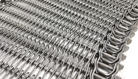
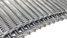
PosiDrive Spiral® is an alternative to Lotension drive systems. PosiDrive Spiral features a stainless-steel grid belt with driving tabs on the inside edge. The tabs engage and are driven by vertical ribs on the spiral center drum. PosiDrive Spiral is recommended particularly for applications where product movement is a problem, or where oils or other product characteristics cause operational issues with Lotension drive systems.
Features
Specifications
Options
Downloads
Features
The positive drive concept of the PosiDrive Spiral keeps belt tensions low which helps increase belt life and allows for increased product load capacity.
The PosiDrive Spiral system allows product dwell time to be easily set using a simplified single speed control and is offered for various cage configurations making it ideal for new spiral systems.
Features Include:
- Engineered inside belt edge designed to securely engage ribbed cage
- Simple to use, easy to adjust single point speed control system
- Steel welded legs that reduce flexibility in the belt
- Self-synchronizing drive eliminates flip-ups
- Easily retrofittable options to minimize conversion downtime
- Factory service support available 24 hours a day, 365 days a year
PosiDrive at a Glance:
- Prevents product movement and disorientation
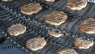
- A perfect solution for oily products
- Designed for processing both heavy and lightweight foods
- Ideal for retrofitting existing proofing, cooling, and freezing spiral applications
DIRECTION
![]()
SPIRAL
APPLICATIONS

FREEZER

SMOKER

COOLER

COOKER

DRYER

PROOFER

BLANCHER

PACKAGING
Does this meet your project needs?
Does this meet your project needs?
Does this meet your project needs?
Let’s get started!
Let’s get started!
Let’s get started!
Specifications
Technical Specifications
Select another product option
| Technical Specifications | Units | Posidrive Grid 100 |
|---|---|---|
| Longitudinal Pitch | in. [mm] | 1.08 [27.4] |
| Minimum Turn Ratio | As low as 2 :1 standard. Turn ratios and configurations must be evaluated by Ashworth Engineering | |
| Turn Capability | Uni-directional (left or right-must specify direction) | |
| Available Widths: Straight | in. [mm] | 12-40 [305-1016]; Wider belts need to be reviewed by Ashworth Engineering. |
| Available Widths: Curve/Spiral | in. [mm] | 12-40 [305-1016]; Wider belts need to be reviewed by Ashworth Engineering. |
| Mode of Turning | Inside edge collapses in turn | |
| Inside Conveying Surface | in. [mm] | Belt Width -2.69 [-68.33] |
| Allowable Tension: Curve/Spiral | lb. [kg] | 200 [91] |
| Allowable Tension: Straight | lb. [kg] | 400 [181] |
Available Sprocket Options
Sprocket Reference
Select another sprocket size
Select a product
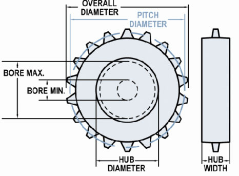
| Nom. Size | Display | Teeth | Pitch Diameter in (mm) | Hub Diameter in (mm) | Bore Min in (mm) | Bore Max in (mm) |
|---|---|---|---|---|---|---|
| 3 | #3-9 Hardened Steel | 9 | 0 | 2.45 (62.23) | 1 (25.4) | 1.83 (46.48) |
| 3 | #3-9 T303 | 9 | 3.16 (80.26) | 2.46 (62.48) | 1 (25.4) | 1.84 (46.74) |
| 3 | #3-9 T303 | 9 | 3.16 (80.26) | 2.46 (62.48) | 1 (25.4) | 1.84 (46.74) |
| 3 | #3-9 T303 | 9 | 3.16 (80.26) | 2.46 (62.48) | 1.25 (31.75) | 1.84 (46.74) |
| 3 | #3-9 T303 | 9 | 3.16 (80.26) | 2.46 (62.48) | 0.94 (23.81) | 1.84 (46.74) |
| 3 | #3-9 T316 | 9 | 3.16 (80.26) | 2.46 (62.48) | 1.44 (36.51) | 1.84 (46.74) |
| 3 | #3-9 UHMW | 9 | 3.16 (80.26) | 2.53 (64.26) | 1 (25.4) | 1.72 (43.69) |
| 3 | #3-9 UHMW | 9 | 3.16 (80.26) | 2.53 (64.26) | 0 | 1.72 (43.69) |
| 4 | #4 UHMW FI | 0 | 0 | 3.92 (99.57) | 0.75 (19.05) | 2.93 (74.42) |
| 4 | #4 UHMW I | 0 | 0 | 3.92 (99.57) | 0 | 2.93 (74.42) |
| 4 | #4-11 T303 | 11 | 3.83 (97.36) | 3.18 (80.72) | 0 | 2.07 (52.58) |
| 4 | #4-11 T303 | 11 | 3.83 (97.36) | 3.18 (80.72) | 0 | 2.44 (61.98) |
| 4 | #4-12 T303 | 12 | 4.17 (105.97) | 3.54 (89.92) | 0 | 2.8 (71.12) |
| 4 | #4-12 T316 | 12 | 4.17 (105.97) | 3.54 (89.92) | 0 | 2.8 (71.12) |
| 4 | #4-12 UHMW | 12 | 4.17 (105.97) | 3.45 (87.63) | 0.75 (19.05) | 2.46 (62.48) |
| 4 | #4-13 Celcon | 13 | 4.4 (111.76) | 3.9 (99.06) | 1 (25.4) | 2.91 (73.91) |
| 4 | #4-13 CI | 13 | 4.53 (115.09) | 3.91 (99.22) | 0 | 3.04 (77.22) |
| 4 | #4-13 T316 | 13 | 4.53 (115.09) | 3.91 (99.22) | 0 | 3.04 (77.22) |
| 4 | #4-13 UHMW | 13 | 4.53 (115.06) | 3.9 (99.06) | 1 (25.4) | 2.91 (73.91) |
| 5 | #5-15 T303 | 15 | 5.2 (131.95) | 4.58 (116.36) | 0 | 3.59 (91.19) |
| 5 | #5-15 UHMW | 15 | 5.2 (131.95) | 4.58 (116.36) | 2 (50.8) | 3.46 (87.88) |
| 6 | #6 UHMW FI | 0 | 0 | 5.65 (143.51) | 0.75 (19.05) | 4.29 (108.97) |
| 6 | #6 UHMW I | 0 | 0 | 5.65 (143.51) | 0 | 4.29 (108.97) |
| 6 | #6-18 CI | 18 | 6.24 (158.5) | 5.66 (143.67) | 0 | 3.75 (95.25) |
| 6 | #6-18 Nylon | 18 | 6.24 (158.5) | 5.65 (143.51) | 1 (25.4) | 4.54 (115.32) |
| 6 | #6-18 T316 | 18 | 6.24 (158.5) | 5.66 (143.67) | 1 (25.4) | 3.75 (95.25) |
| 6 | #6-18 UHMW | 18 | 6.24 (158.5) | 5.65 (143.51) | 0 | 4.29 (108.97) |
| 6 | #6-18 UHMW FS | 18 | 6.15 (156.16) | 5.65 (143.46) | 0 | 4.29 (108.97) |
| 6 | #6-18 UHMW Product Release | 18 | 6.4 (162.51) | 5.65 (143.46) | 1 (25.4) | 4.29 (108.97) |
| 6 | #6-18 UHMW Split | 18 | 6.24 (158.5) | 5.65 (143.46) | 0 | 4.29 (108.97) |
| 6 | #6-19 T303 | 19 | 6.55 (166.47) | 6.03 (153.21) | 0 | 4.8 (121.92) |
| 6 | #6-19 UHMW | 19 | 6.55 (166.47) | 6.03 (153.21) | 1.18 (30) | 4.67 (118.62) |
| 8 | #8 UHMW FI | 0 | 0 | 7.38 (187.45) | 0.75 (19.05) | 5.89 (149.61) |
| 8 | #8 UHMW I | 0 | 0 | 7.38 (187.45) | 0 | 5.89 (149.61) |
| 8 | #8-23 CI | 23 | 7.41 (188.11) | 7.41 (188.11) | 0 | 5.9 (149.86) |
| 8 | #8-23 CI | 23 | 7.96 (202.18) | 7.41 (188.12) | 0 | 4.75 (120.65) |
| 8 | #8-23 T316 | 23 | 7.96 (202.18) | 7.41 (188.12) | 0 | 4.75 (120.65) |
| 8 | #8-23 T316 | 23 | 7.97 (202.41) | 7.41 (188.12) | 1 (25.4) | 4.75 (120.65) |
| 8 | #8-23 UHMW | 23 | 7.96 (202.18) | 7.39 (187.71) | 1 (25.4) | 5.9 (149.86) |
| 8 | #8-23 UHMW Split | 23 | 7.89 (200.33) | 7.39 (187.63) | 0 | 5.9 (149.86) |
| 10 | #10-31 CI | 31 | 10.72 (272.29) | 10.16 (258.06) | 0 | 8.67 (220.22) |
| 10 | #10-31 T316 | 31 | 10.72 (272.29) | 10.16 (258.06) | 0 | 8.67 (220.22) |
| 10 | #10-31 UHMW | 31 | 10.66 (270.76) | 10.16 (258.06) | 0.99 (25.02) | 8.42 (213.87) |
| 12 | #12-37 UHMW | 37 | 12.74 (323.49) | 12.24 (310.79) | 0.99 (25.02) | 10.49 (266.45) |
NOTES:
- UHMWPE material type components have a 150°F [66°C] maximum operating temperature.
- Maximum bore sized listed for UHMWPE material is based on 1/2 inch [12.7 mm] of material above keyway.
FILLER ROLLS:
- 4-3/16 inch [106 mm] diameter filler rolls recommended with #4-13 tooth sprockets
- 5-7/8 inch [149 mm] diameter filler rolls recommended with #6-18 tooth sprockets
- 7-5/8 inch [193 mm] diameter filler rolls recommended with #8-23 tooth sprockets
Supports
As a rule, support rails are required, with maximum spacings of 18 inches [457.2 mm] on the load side and 24 inches [609.9 mm] on the return side. Rollers may also be used. For light loads, support rails may be placed farther apart - consult Ashworth Engineering for your particular application.
Material Reference
- Acetal - polyoxymethylene plastic
- Celcon - acetal copolymer
- CI - cast iron
- Hardened Steel
- Nylon
- T303 - stainless steel
- T316 - stainless steel
- UMHW - polyethylene plastic
Belt Calculator
No Results
Base Belt Weight
Belt Pitch
Turn Ratio
Belt Strength
Min Filler Roll Diameter
Conveying Surface
Inside Conveying Surface
Outside Conveying Surface
Mesh Opening Size
Open Area Surface
Open Area Thru
Need more detailed information?
Need more detailed information?
Need more detailed information?
Options
Product Options
Special Spirals (Patented)
-
Available in Omni-Tough® overlay only
- Available in 16 fa. and 17 ga. only
-
One or more spirals on conveying surface are raised
-
Used as guard edges, lane dividers, or flights
-
Maximum height 1 inch [25.4 mm]
-
Available options: height, spacing, location, shape, and number of lanes in belt

Does this meet your project needs?
Does this meet your project needs?
Does this meet your project needs?
Let’s get started!
Let’s get started!
Let’s get started!
Downloads
Downloads

Conveyor System Review Form
Features
The positive drive concept of the PosiDrive Spiral keeps belt tensions low which helps increase belt life and allows for increased product load capacity.
The PosiDrive Spiral system allows product dwell time to be easily set using a simplified single speed control and is offered for various cage configurations making it ideal for new spiral systems.
Features Include:
- Engineered inside belt edge designed to securely engage ribbed cage
- Simple to use, easy to adjust single point speed control system
- Steel welded legs that reduce flexibility in the belt
- Self-synchronizing drive eliminates flip-ups
- Easily retrofittable options to minimize conversion downtime
- Factory service support available 24 hours a day, 365 days a year
PosiDrive at a Glance:
- Prevents product movement and disorientation
- A perfect solution for oily products
- Designed for processing both heavy and lightweight foods
- Ideal for retrofitting existing proofing, cooling, and freezing spiral applications
DIRECTION
![]()
SPIRAL
APPLICATIONS
FREEZER
SMOKER
COOLER
COOKER
DRYER
PROOFER
BLANCHER
PACKAGING
Does this meet your project needs?
Does this meet your project needs?
Does this meet your project needs?
Let’s get started!
Let’s get started!
Let’s get started!
Specifications
Technical Specifications
Select another product option
| Technical Specifications | Units | Posidrive Grid 150 |
|---|---|---|
| Longitudinal Pitch | in. [mm] | 1.50 [38.1] |
| Minimum Turn Ratio | As low as 2 :1 standard. Turn ratios and configurations must be evaluated by Ashworth Engineering | |
| Turn Capability | Uni-directional (left or right-must specify direction) | |
| Available Widths: Straight | in. [mm] | 12-54 [305-1372]; Wider belts need to be reviewed by Ashworth Engineering. |
| Available Widths: Curve/Spiral | in. [mm] | 12-54 [305-1372]; Wider belts need to be reviewed by Ashworth Engineering. |
| Mode of Turning | Inside edge collapses in turn | |
| Inside Conveying Surface | in. [mm] | Belt Width -3.03 [-76.96] |
| Allowable Tension: Curve/Spiral | lb. [kg] | 400 [181] |
| Allowable Tension: Straight | lb. [kg] | 800 [363] |
Available Sprocket Options
Sprocket Reference
Select another sprocket size
Select a product
| Nom. Size | Display | Teeth | Pitch Diameter in (mm) | Hub Diameter in (mm) | Bore Min in (mm) | Bore Max in (mm) |
|---|---|---|---|---|---|---|
| 6 | #6 UHMW FI | 0 | 0 | 5.5 (139.7) | 0.75 (19.05) | 4.14 (105.16) |
| 6 | #6 UHMW I | 0 | 0 | 5.5 (139.7) | 0.75 (19.05) | 4.14 (105.16) |
| 6 | #6-13 UHMW Not Recommended | 13 | 6.27 (159.26) | 5.5 (139.7) | 0 | 4.14 (105.16) |
| 8 | #8 UHMW FI | 0 | 0 | 7.43 (188.72) | 0 | 5.94 (150.88) |
| 8 | #8 UHMW I | 0 | 0 | 7.43 (188.72) | 0.75 (19.05) | 5.94 (150.88) |
| 8 | #8-17 T303 | 17 | 8.16 (207.26) | 7.43 (188.72) | 0 | 5.95 (151.13) |
| 8 | #8-17 UHMW | 17 | 8.16 (207.26) | 7.43 (188.72) | 0.75 (19.05) | 5.94 (150.88) |
NOTES:
- UHMWPE material type components have a 150°F [66°C] maximum operating temperature.
- Maximum bore sized listed for UHMWPE material is based on 1/2 inch [12.7 mm] of material above keyway.
FILLER ROLLS:
- 7-5/8 inch [193 mm] diameter filler rolls recommended with #8-23 tooth sprockets
Supports
As a rule, support rails are required, with maximum spacings of 18 inches [457.2 mm] on the load side and 24 inches [609.9 mm] on the return side. Rollers may also be used. For light loads, support rails may be placed farther apart - consult Ashworth Engineering for your particular application.
Material Reference
- Acetal - polyoxymethylene plastic
- Celcon - acetal copolymer
- CI - cast iron
- Hardened Steel
- Nylon
- T303 - stainless steel
- T316 - stainless steel
- UMHW - polyethylene plastic
Belt Calculator
No Results
Base Belt Weight
Belt Pitch
Turn Ratio
Belt Strength
Min Filler Roll Diameter
Conveying Surface
Inside Conveying Surface
Outside Conveying Surface
Mesh Opening Size
Open Area Surface
Open Area Thru
Need more detailed information?
Need more detailed information?
Need more detailed information?
Options
Product Options
Special Spirals (Patented)
-
Available in Omni-Tough® overlay only
- Available in 16 fa. and 17 ga. only
-
One or more spirals on conveying surface are raised
-
Used as guard edges, lane dividers, or flights
-
Maximum height 1 inch [25.4 mm]
-
Available options: height, spacing, location, shape, and number of lanes in belt
Does this meet your project needs?
Does this meet your project needs?
Does this meet your project needs?
Let’s get started!
Let’s get started!
Let’s get started!
Downloads
Downloads
Conveyor System Review Form
Features
The positive drive concept of the PosiDrive Spiral keeps belt tensions low which helps increase belt life and allows for increased product load capacity.
The PosiDrive Spiral system allows product dwell time to be easily set using a simplified single speed control and is offered for various cage configurations making it ideal for new spiral systems.
Features Include:
- Engineered inside belt edge designed to securely engage ribbed cage
- Simple to use, easy to adjust single point speed control system
- Steel welded legs that reduce flexibility in the belt
- Self-synchronizing drive eliminates flip-ups
- Easily retrofittable options to minimize conversion downtime
- Factory service support available 24 hours a day, 365 days a year
PosiDrive at a Glance:
- Prevents product movement and disorientation
- A perfect solution for oily products
- Designed for processing both heavy and lightweight foods
- Ideal for retrofitting existing proofing, cooling, and freezing spiral applications
DIRECTION
![]()
SPIRAL
APPLICATIONS
FREEZER
SMOKER
COOLER
COOKER
DRYER
PROOFER
BLANCHER
PACKAGING
Does this meet your project needs?
Does this meet your project needs?
Does this meet your project needs?
Let’s get started!
Let’s get started!
Let’s get started!
Specifications
Technical Specifications
Select another product option
| Technical Specifications | Units | Small Radius Posidrive Grid 100 |
|---|---|---|
| Longitudinal Pitch | in. [mm] | 1.08 [27.4] |
| Minimum Turn Ratio | As low as 1 :1 standard. Turn ratios and configurations must be evaluated by Ashworth Engineering | |
| Turn Capability | Uni-directional (left or right-must specify direction) | |
| Available Widths: Straight | in. [mm] | 14-48 [356-1219]; Wider belts need to be reviewed by Ashworth Engineering. |
| Available Widths: Curve/Spiral | in. [mm] | 14-48 [356-1219]; Wider belts need to be reviewed by Ashworth Engineering. |
| Mode of Turning | Inside edge collapses in turn | |
| Inside Conveying Surface | in. [mm] | Belt Width -1.93 [-49.02] |
| Allowable Tension: Curve/Spiral | lb. [kg] | 150 [68] |
| Allowable Tension: Straight | lb. [kg] | 300 [136] |
Available Sprocket Options
Sprocket Reference
Select another sprocket size
Select a product
| Nom. Size | Display | Teeth | Pitch Diameter in (mm) | Hub Diameter in (mm) | Bore Min in (mm) | Bore Max in (mm) |
|---|---|---|---|---|---|---|
| 3 | #3-9 Hardened Steel | 9 | 0 | 2.45 (62.23) | 1 (25.4) | 1.83 (46.48) |
| 3 | #3-9 T303 | 9 | 3.16 (80.26) | 2.46 (62.48) | 1 (25.4) | 1.84 (46.74) |
| 3 | #3-9 T303 | 9 | 3.16 (80.26) | 2.46 (62.48) | 1 (25.4) | 1.84 (46.74) |
| 3 | #3-9 T303 | 9 | 3.16 (80.26) | 2.46 (62.48) | 1.25 (31.75) | 1.84 (46.74) |
| 3 | #3-9 T303 | 9 | 3.16 (80.26) | 2.46 (62.48) | 0.94 (23.81) | 1.84 (46.74) |
| 3 | #3-9 T316 | 9 | 3.16 (80.26) | 2.46 (62.48) | 1.44 (36.51) | 1.84 (46.74) |
| 3 | #3-9 UHMW | 9 | 3.16 (80.26) | 2.53 (64.26) | 1 (25.4) | 1.72 (43.69) |
| 3 | #3-9 UHMW | 9 | 3.16 (80.26) | 2.53 (64.26) | 0 | 1.72 (43.69) |
| 4 | #4 UHMW FI | 0 | 0 | 3.92 (99.57) | 0.75 (19.05) | 2.93 (74.42) |
| 4 | #4 UHMW I | 0 | 0 | 3.92 (99.57) | 0 | 2.93 (74.42) |
| 4 | #4-11 T303 | 11 | 3.83 (97.36) | 3.18 (80.72) | 0 | 2.07 (52.58) |
| 4 | #4-11 T303 | 11 | 3.83 (97.36) | 3.18 (80.72) | 0 | 2.44 (61.98) |
| 4 | #4-12 T303 | 12 | 4.17 (105.97) | 3.54 (89.92) | 0 | 2.8 (71.12) |
| 4 | #4-12 T316 | 12 | 4.17 (105.97) | 3.54 (89.92) | 0 | 2.8 (71.12) |
| 4 | #4-12 UHMW | 12 | 4.17 (105.97) | 3.45 (87.63) | 0.75 (19.05) | 2.46 (62.48) |
| 4 | #4-13 Celcon | 13 | 4.4 (111.76) | 3.9 (99.06) | 1 (25.4) | 2.91 (73.91) |
| 4 | #4-13 CI | 13 | 4.53 (115.09) | 3.91 (99.22) | 0 | 3.04 (77.22) |
| 4 | #4-13 T316 | 13 | 4.53 (115.09) | 3.91 (99.22) | 0 | 3.04 (77.22) |
| 4 | #4-13 UHMW | 13 | 4.53 (115.06) | 3.9 (99.06) | 1 (25.4) | 2.91 (73.91) |
| 5 | #5-15 T303 | 15 | 5.2 (131.95) | 4.58 (116.36) | 0 | 3.59 (91.19) |
| 5 | #5-15 UHMW | 15 | 5.2 (131.95) | 4.58 (116.36) | 2 (50.8) | 3.46 (87.88) |
| 6 | #6 UHMW FI | 0 | 0 | 5.65 (143.51) | 0.75 (19.05) | 4.29 (108.97) |
| 6 | #6 UHMW I | 0 | 0 | 5.65 (143.51) | 0 | 4.29 (108.97) |
| 6 | #6-18 CI | 18 | 6.24 (158.5) | 5.66 (143.67) | 0 | 3.75 (95.25) |
| 6 | #6-18 Nylon | 18 | 6.24 (158.5) | 5.65 (143.51) | 1 (25.4) | 4.54 (115.32) |
| 6 | #6-18 T316 | 18 | 6.24 (158.5) | 5.66 (143.67) | 1 (25.4) | 3.75 (95.25) |
| 6 | #6-18 UHMW | 18 | 6.24 (158.5) | 5.65 (143.51) | 0 | 4.29 (108.97) |
| 6 | #6-18 UHMW FS | 18 | 6.15 (156.16) | 5.65 (143.46) | 0 | 4.29 (108.97) |
| 6 | #6-18 UHMW Product Release | 18 | 6.4 (162.51) | 5.65 (143.46) | 1 (25.4) | 4.29 (108.97) |
| 6 | #6-18 UHMW Split | 18 | 6.24 (158.5) | 5.65 (143.46) | 0 | 4.29 (108.97) |
| 6 | #6-19 T303 | 19 | 6.55 (166.47) | 6.03 (153.21) | 0 | 4.8 (121.92) |
| 6 | #6-19 UHMW | 19 | 6.55 (166.47) | 6.03 (153.21) | 1.18 (30) | 4.67 (118.62) |
| 8 | #8 UHMW FI | 0 | 0 | 7.38 (187.45) | 0.75 (19.05) | 5.89 (149.61) |
| 8 | #8 UHMW I | 0 | 0 | 7.38 (187.45) | 0 | 5.89 (149.61) |
| 8 | #8-23 CI | 23 | 7.41 (188.11) | 7.41 (188.11) | 0 | 5.9 (149.86) |
| 8 | #8-23 CI | 23 | 7.96 (202.18) | 7.41 (188.12) | 0 | 4.75 (120.65) |
| 8 | #8-23 T316 | 23 | 7.96 (202.18) | 7.41 (188.12) | 0 | 4.75 (120.65) |
| 8 | #8-23 T316 | 23 | 7.97 (202.41) | 7.41 (188.12) | 1 (25.4) | 4.75 (120.65) |
| 8 | #8-23 UHMW | 23 | 7.96 (202.18) | 7.39 (187.71) | 1 (25.4) | 5.9 (149.86) |
| 8 | #8-23 UHMW Split | 23 | 7.89 (200.33) | 7.39 (187.63) | 0 | 5.9 (149.86) |
| 10 | #10-31 CI | 31 | 10.72 (272.29) | 10.16 (258.06) | 0 | 8.67 (220.22) |
| 10 | #10-31 T316 | 31 | 10.72 (272.29) | 10.16 (258.06) | 0 | 8.67 (220.22) |
| 10 | #10-31 UHMW | 31 | 10.66 (270.76) | 10.16 (258.06) | 0.99 (25.02) | 8.42 (213.87) |
| 12 | #12-37 UHMW | 37 | 12.74 (323.49) | 12.24 (310.79) | 0.99 (25.02) | 10.49 (266.45) |
NOTES:
- UHMWPE material type components have a 150°F [66°C] maximum operating temperature.
- Maximum bore sized listed for UHMWPE material is based on 1/2 inch [12.7 mm] of material above keyway.
- One sprocket will engage the inside row of links and one sprocket will engage the middle row of links.
- One toothless flanged idler support roll supports the outside row of links.
FILLER ROLLS:
- 4-3/16 inch [106 mm] diameter filler rolls recommended with #4-13 tooth sprockets
- 5-7/8 inch [149 mm] diameter filler rolls recommended with #6-18 tooth sprockets
- 7-5/8 inch [193 mm] diameter filler rolls recommended with #8-23 tooth sprockets
Supports
As a rule, support rails are required, with maximum spacings of 18 inches [457.2 mm] on the load side and 24 inches [609.9 mm] on the return side. Rollers may also be used. For light loads, support rails may be placed farther apart - consult Ashworth Engineering for your particular application.
Material Reference
- Acetal - polyoxymethylene plastic
- Celcon - acetal copolymer
- CI - cast iron
- Hardened Steel
- Nylon
- T303 - stainless steel
- T316 - stainless steel
- UMHW - polyethylene plastic
Belt Calculator
No Results
Base Belt Weight
Belt Pitch
Turn Ratio
Belt Strength
Min Filler Roll Diameter
Conveying Surface
Inside Conveying Surface
Outside Conveying Surface
Mesh Opening Size
Open Area Surface
Open Area Thru
Need more detailed information?
Need more detailed information?
Need more detailed information?
Options
Product Options
Special Spirals (Patented)
-
Available in Omni-Tough® overlay only
- Available in 16 fa. and 17 ga. only
-
One or more spirals on conveying surface are raised
-
Used as guard edges, lane dividers, or flights
-
Maximum height 1 inch [25.4 mm]
-
Available options: height, spacing, location, shape, and number of lanes in belt
Does this meet your project needs?
Does this meet your project needs?
Does this meet your project needs?
Let’s get started!
Let’s get started!
Let’s get started!
Downloads
Downloads
Conveyor System Review Form


