


Ashworth OGBL Conveyor Belting is the Versatile, Quality Line of Steel Eye-Link Belts.
Eye-Link Belts
Ashworth OGB and OGB-L Plus are straight running, positively driven, quality eye link belts for either industrial or food processing applications. Available in an exceptionally wide array of materials, wire diameters, surface treatments and accessories, these versatile steel conveyor belts can be designed and manufactured to satisfy the most demanding of applications.
Eye-Link Belts
Features
Specifications
Options
Downloads
Features
QUALITY MAKES THE DIFFERENCE
OGBL belts are naturally straight running and provide an extremely flat surface, promoting smooth and easy product conveyance across the entire width of the belt. OGBL Plus is our extra strong, USDA-approved eye link belt, with available tension ratings of up to 260lbs per link row.
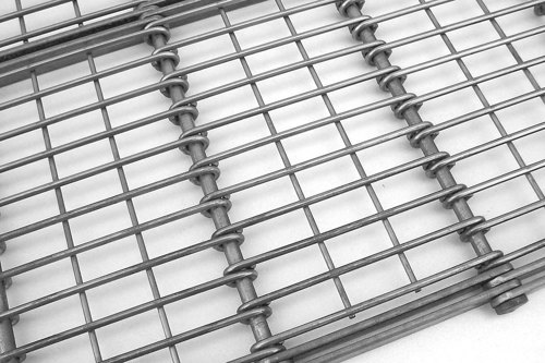
EXTREMELY OPEN AND SANITARY
While OGBL and OGBL Plus belts can be made in some comparatively closed configurations to provide excellent small product support, they can also be configured into some of the most open designs available. Our "U.S. Design" variant features alternating rows of eye links that are fully separated from one another for the easiest possible cleaning. As a result, OGBL conveyor belts are great for use in applications demanding high air flow coupled with high sanitary requirements, as in freezing poultry products. And with their high tension ratings, they are also the belt of choice for bottling pasteurizing applications.
Versatile Design
- Available in numerous configurations of pitch spacing, wire diameter, and mesh designs
- Options include cross flights, side plates, chain edges, and additional bar links for increased strength
Inherently Strong
- Extremely durable with tension ratings up to 260lb. per link row
- Roller drive system engages the entire width of the belt, increasing tension capabilities and belt life
Precise Conveying
- Positively driven for true tracking
- Flat, even surface and rigid structure resisting side-to-side deflection delivers smooth product conveyance
Product Applications
-
Cooker Belts
-
Tunnel Freezer Conveyor Belts
-
Cooling Belts
-
Drying and Drainage Belts
-
Pasteurizer Belts
DIRECTION

STRAIGHT RUN
APPLICATIONS

FREEZER

SMOKER

COOLER

DRYER

PROOFER

BLANCHER

PASTEURIZING

PACKAGING
Does this meet your project needs?
Does this meet your project needs?
Does this meet your project needs?
Let’s get started!
Let’s get started!
Let’s get started!
Specifications
Technical Specifications
| Technical Specifications | Units | |
|---|---|---|
| Available Materials | 304, 316 stainless steel, carbon, other materials available upon request | |
| Longitudinal Pitch Lengths | in. (mm) | 1.00 (25.4), 1.18 (30.0), 1.97 (50.0), 2.00 (50.8), 2.95 (75.0) |
| Eye Link Wire Diameters | in. (mm) | 0.08 (2.0), 0.10 (2.5), 0.12 (3.0), 0.14 (3.5) |
| Cross Rod Diameters | in. (mm) | 0.16 (4.0), 0.20 (5.0), 0.28 (7.0), 0.32 (8.0) |
| Available Widths | in. (mm) | 2.0-244.0 (50.8-6197.6) |
| Conveying Surface | in. (mm) | Full belt width minus 0.32 (8.1) |
| Weight | Dependent upon construction - Contact Ashworth Engineering | |
| Maximum Allowable Tension | Dependent upon construction - Contact Ashworth Engineering | |
|
Maximum Temperature (Material Dependent) |
°F (°C) | Up to 752 (400) |
| Method of Drive | Positively driven |
Mesh Designations
Mesh configurations for Eye-Link belts are designated as in the following example (Figure 20):
A x M/C-D
50 x 10/2.5-5
Where:
50 = Belt's longitudinal pitch in mm
10 = Distance between eye links in mm
2.5 = Eye link wire diameter in mm
5 = Cross rod diameter in mm

Sprockets
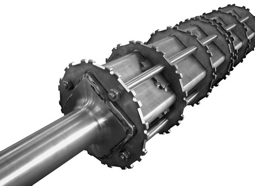
Eye-Link belts are positively driven with sprockets situated across the width of the belt. Sprockets should be positioned at a 15 mm (0.59") offset next to the bar links rows at both sides. For all Eye-Link belts, 8 or 12 tooth sprockets are standard. Sprockets can be produced from carbon steel, stainless steel and UHMWPE. The number of teeth can vary from 8 to 30 teeth.
For wide belts, the use of sprocketed drums or pulleys is recommended based on the maximum allowable deflection of the drum. For use of Eye-Link belts in environments where formation of ice is possible, a special ice-free sprocket is available to prevent ice build-up. for wide belts in an ice-containing environment, a cage drum is typically used.
Wear Strip Material & Placement
The recommended belt supports for Eye-Link belts operated at temperatures from -40°F (-40°C) to 140°F (60°C) are UHMWPE strips placed underneath the bar links. The strips should be at least 0.59" (15 mm) wider than the total width of one bar link packet.
For temperatures over 140°F (60°C), the recommended material is Inoxyda (glide bronze) for non-food applications and stainless steel for food applications.
System Requirements
- Eye-Link belts do not normally need a tension unit. Preferably, there is a catenary sag over the rollers.
- Reverse bends should be avoided, as this will damage the eye links.
- Heavy products must not fall on the belt as this could damage the eye links and cross wires.
- The drive and return drum should be placed 0.08" (2 mm) highter then the support strips.
- All drums and rollers must be parallel to each other.
- The support bed must be horizontal to ensure correct tracking of the belt
- The maximum recommended belt speed is 60 ft/min. (20 m/min) depending on belt width, load, and system layout.
Available Options
Designs
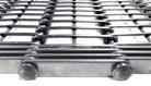
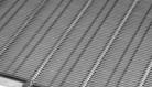
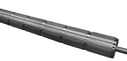
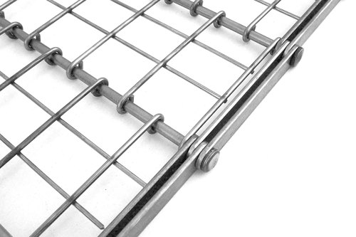
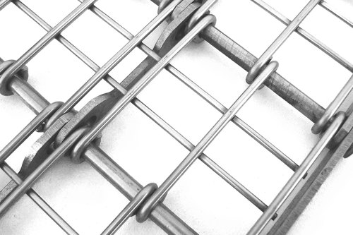
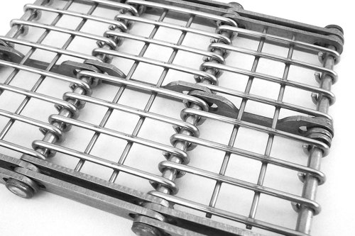
Eye-Link belts are available in either EU (standard) or US designs, the construction of which is based on the placement of the eye links throughout the belt. In the US design, the eye-link ends are equally spaced apart; whereas the EU design, the eye links are placed so the ends are in direct contact with one another. EU design belts display a more closed grid pattern, while the US design is more open, as in the following photographs.
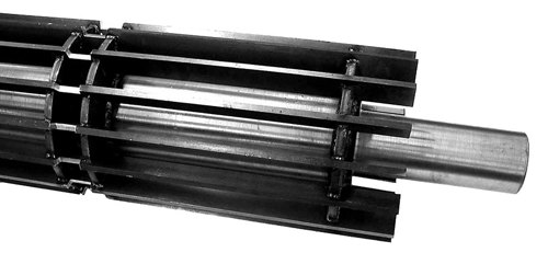
Eye-Link Plus
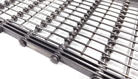
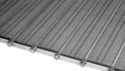
Eye-Link Plus belts are constructed with specially designed internal bar links that have slotted holes and are cut to allow the belt's cross wires to pass unimpeded across the width of the module. This design adds strength to the belt while enabling excellent cleanability. Eye-Link Plus belts are only available in 50 mm pitch, but can be manufactured in either EU or US eye link patterns as shown in the accompanying photographs.

Loose Chain & Chain Edges
All Eye-Link belts can be fitted with either loose chain made from bar links or with chain edges to suit customer specifications.
Cross Flights
Cross flights (Figure 21) prevent product from sliding or rolling down the belt when operated on an incline/decline. typical construction includes a support plate along each belt edge, with a flat bar welded onto the edge of the plate, almost extending across the full width of the belt

Side Plates
Side plates (Figure 22) prevent product from falling of the edges of the belt. Standard construction is a plate extending 41 mm (1.61"), 51 mm (2.01"), or 61 mm (2.4") above the belts surface. Non-standard side plates are possible from 10 mm (0.39") up to 200 mm (7.87") and are manufactured per order. Size plates replace one bar link at the belt edge.

Bar Links
Bar links (Figure 23) provide tension carrying capacity. They also prevent excessive cross rod and module deflection. Additional bar links may be added to strengthen the belt. the built should be supported under the bar links only. For Eye-Link Plus, the inner bar links are cut out in the middle to provide room for a continuous module. All bar links are fitted with slotted holds for easy cleaning.
Need more detailed information?
Need more detailed information?
Need more detailed information?
Options
Product Options
Guard Edges
Guard edges are located on the inside of the chain. Height above the belt surface and material is customer specified. Guard edges are usually used with round cross supports (rods, turned down rods, or pipe/ rod) which are inserted through holes in the guard edge.
Guard edges are generally plates that may be offset, of interlocking design, or flat plates that are assembled in either a shingled or staggered arrangement. Plates can be square or rectangular and either flared or notched as required (Figure 18). Plates with double tabs may be used. The bottom tabs may be inserted through the mesh or the tabs may straddle the mesh and are welded or brazed to it. Whenever guard edges are specified, the inside guard edge (IGE) dimension should be specified by the customer.
Flights (Lifts or Cleats)
Generally, flights are attached to the belt by welding or brazing them to the mesh and/or the guard edges (if applicable). The style, material, height, and spacing above the belt surface is customer specified. The length of the flight is usually the same as the mesh width but can be narrower if specified.
Usually, flights are produced from formed angle stock, although commercially available flat bar, keystock, cut sheet metal, or other customer specified shapes may be used. Angle types usually have slots or holes punched in the bottom to facilitate plug-welding to the mesh. It should be noted that flights are not meant to carry product up inclines but are just to prevent product slippage.
Wipers
Wiper attachments, typically fabricated from wire mesh, hang from the bottom surface of the belt to wipe debris from drip pans, trays, bins, etc. These attachments are typically attached to belt mesh with a straight or crimped connector rod. Mesh designation (if applicable), material, length below belt surface, width of wiper, and spacing are customer specified.
Does this meet your project needs?
Does this meet your project needs?
Does this meet your project needs?
Let’s get started!
Let’s get started!
Let’s get started!
Downloads
Downloads
Product Sheets

Technical Bulletins
Conveyor System Review Form
Other


